<< Previous | Garden Scale | Beginnings | New Beginnings | Third Incarnation | Additions | Pond | Downtown | Expansion | Tower | Future | Next >>
Adding A Control Tower To Our Model Railroad Empire
Still having fun with this?
Most of what I've described previously has been something directly added to the railroad itself. Stringers. Track. Ballast. Power Feeds. Trestles and a bridge. Cars and engines. Mainly things that add to our enjoyment of the Barkyard Railroad directly. Once the work is completed or the items added, we're ready to once again run trains. This enhancement is different and the same... Wait. What? It's the same in that it will become part of the railroad, but different in that it will stay on the patio, and not be part of the railroad in operation. It will be how we operate the railroad, and as such still be enjoyed for its scale model value as it sits on the patio, albeit twice as large in scale as the railroad.
I'm still trying to finalize the plans for the proper scale architecture, but I'll get to that in a bit. All of the wood I've used to model structures, like ties and trestle bents and such, are old fence panels repurposed into scale lumber. In this case, I'm using ¾" exterior grade plywood, mainly because I had it on hand and the ½" seemed way too flimsy... Well, not so much flimsy as warped and in need of internal bracing to hold its shape. Since I'm using the Bachmann "Big Haulers", which are large and meant to represent narrow gauge equipment rather than standard gauge, you could say what I'm modelling is closer to F scale than G scale - Meaning 1:20.3 rather than 1:29 or 1:32 proportions.
I tend to use 1:24, or "half inch", sometimes called half doll house scale, since it makes the math a little easier. More like it makes the scale lumber a standard fractional size. For example, a scale 6x12 is ¼"x½", the size of a trestle sill member. Cross bracing for trestles is generally 3x10 or 3x12, making it 1⁄8"x3⁄16" or 1⁄8"x¼". And 1⁄8" is about as small as I feel comfortable ripping on the table saw. I make a push shoe from ¾" plywood and keep it just for doing 1⁄8" - ¼" sized material. Another is dedicated to the ¼" - ½" range. Much bigger than that and I can just use the standard push stick that came with the table saw.
Much smaller than 1⁄8" and I'll need one of those Northwest Shortline "chopper thingies" to slice the pieces using razor blades and such. I think they may actually make a mini table saw of sorts for ripping stock in those smaller sizes, like scale 2z4s and the like. The alternative is to buy the expensive precut scale lumber. For now I'm just sticking with the sizes I can cut on the table saw. Thankfully most everything about the railroad is massive already. And since I build to a scale slightly smaller than the equipment I'm running, it will look more rickety. On the flip side, if I ever decide to run standard gauge equipment, it's going to look MASSIVE compared to the trains.
In any case, the control tower needs to stand as tall as a side table, as one would be sitting on the patio to use it to control the railroad operation. A two story structure, say roughly twenty feet tall, would be slightly less than a foot tall using 1:24 scale. Add the roof peak and we're right at a foot tall, but still too short to avoid having to bend over to use it, or have it sit on a stand or table of its own. Using standard doll house scale of 1:12 puts it right at two feet tall and right at arm's reach. Now to better capture the dimensions and appearance of WALL tower, the West ALLiance interlocking tower that my great uncle used to work at, in the small town in Ohio I grew up in.
Growing up in NE Ohio, my great grandfather and great uncle worked for the railroad. I barely remember my great grandfather, but I do remember visiting there after church sometimes, just down the road a piece from WALL tower. WALL tower guarded the north-south NYC mainline crossing over the east-west PRR mainlines. My brothers and I used to ride our bicycles down to visit him at work until it was torn down in 1972. It was exciting sitting way up above the tracks and watching the trains go by on the tracks below. I still remember him letting us throw the double knife blade switch to activate the crossing signals when a train was approaching.
After its demolition, he was relocated downtown to the station, working as a dispatcher. We still paid him visits, but it soon became apparent that he was way too busy in his dispatcher role to entertain visitors. At just ten years old, I was too young at the time to understand the importance of getting pictures and measurements before the opportunity was gone for good. So as a means of honoring his memory, and some history at the same time, I have to rely on a handful of pictures, counting the number of clapboards, just to guesstimate the dimensions! Thankfully my Aunt JoAnn had those old Polaroids scanned. I'm "reverse engineering" the drawings since the actual drawing are long since lost to time. I guess you could say I'm "recreating history"...
The thing that I really need to recreate is this larger scale interlocking tower to house all the controls. Just the electronics at first, and at this point, it would just be a set of 70VA powerpacks. The entire layout is just one big block at the moment, so eventually I'll need to divide it into smaller blocks, insulating them from one another and running the power feeds to each of them. This is where converting to DCC would help reduce the wiring complexity. For some reason, DCC is still quite expensive for large scale, perhaps because the numbers aren't there for greater economies of scale. Dunno. Wire and switches are still much checper than even the least expensive DCC contoller, not to mention all the trouble and complexity with installing decoders and all, so it's little wonder many folks still prefer low cost DC cabs to expensive DCC setups.
I've seen more folks go with battery power and radio control rather than rely on power through the rails and DCC. What I'd like to do eventually is control each block with its own motor controller electronics and an "intelligent" control system to track each train and its progress, switching control of each block to the cab controlling that train, be it DC or DCC. This would require occupancy detection as well as some sort of ID and feedback. That's where I need a new idea... DCC has expanded to transpond, and could probably identify itself when queried by the controller. The block that received the response would provide the whereabouts of at least one engine of the train. But where is the rest of the train? To the east or to the west of that engine?
Proper occupancy detection for the entire train would require "leakage" resistors to draw a small amount of current to allow the motor controller or other circuitry to detect it. I see this as a work in progress type of project, where features are added as they become available. The "smarts" for the intelligent controller could come from an embedded controller, like a PIC or similar, like an arduino, all the way up to a raspberry pi connected to a flat panel display. The possibilites are endless. For now I would be happy with a tower that had a flip open top and a power pack dedicated and connected to the railroad where I could run trains at the flip of a switch. What would be killer is interlocking lever frames with an entire operational mechanical interlocking and actuation of remote devices, like turnouts and semaphores. Someday...
<< Previous | Garden Scale | Beginnings | New Beginnings | Third Incarnation | Additions | Pond | Downtown | Expansion | Tower | Future | Next >>
So now I'm thinking about how the guys in the smaller scales epoxy those "chip" resistors across the metal wheelsets to provide a current path for sensing and detection. I've also seen some modellers actually add RFID to their rolling stock to track their wherabouts. Maybe the two could be coupled together somehow, like a transponder the size of one of those chip resistors. The problem would be how to program them to be different "addresses", to have a different id in other words. Many embedded devices these days have a sort of serial computer interface, such as "I2C" or the like. It would probably require a socket of sorts to place it in just to program it, and I'm not sure how you would reprogram it once epoxied in place, but I certainly like the idea of each car have its own id and the ability to transpond its location. Again, someday...
In researching block occupancy and transponding, I have found a number of techniques that measure the current draw, all the "same old same old" techniques - Twin-T, reversed diodes, inductive sensing, optical - all "tried and true", all with many sources of manufacture. What I did find intriguing was a new addition to DCC transponding, a means of identifying what block a train is located in when it transponds its response to a DCC command. It still needs block detection, but a new "receiver" is added to the mix that decodes the transponded response and identifies the block that the response came from. Clever. But how does it know where the end of the train is? A light decoder with transponding built into the caboose? What if your pike doesn't run a caboose anymore, like the modern prototype? A block is a rather large chunk of "rail estate" too.
But again, all of this is future expansion. I am currently working on a modified version of Nick's WiFi Train Controller, which I'm calling WiFi Block Controller. Imaginitive, I know... In any case, he found a new current sensing technology that I didn't even know existed, a hall effect based current sensor without all the pitfalls of other inline sensors. Pitfalls like a diode drop of 0.7V or having to insert a power resistor in shunt configuration and somehow isolate the noise of the track from the sensing op amps or associated circuitry. But none of this is getting me any closer to having the actual control tower to house even a simple power pack. And what still needs addressed is how to connect the railroad feeds to it and it to a power supply.
So far, I've been concentrating on constructing the tower itself, perhaps a bit too much. At least, when it comes to the long banks of windows, but I'm jumping ahead a bit...
(Thursday, 27 December 2018)
I started out by making drawings of the Wall Tower to try to get some semblance of a control tower planned and built.
Now whether I get this finished or not during the Christmas break is a different story! These drawings, while detailed,
can take quite a long time to create. Part of the problem I'm having is trying to "guesstimate" the dimensions with
nothing but architectural knowledge and visual clues from a handful of photographs my Aunt JoAnn gave me some years
back. For example, I can say with a good amount of certainty that the wall studs are 16" on center.
Pretty much every inhabited structure I've dealt with has that arrangement, save our house in Wekiva, which used 24" centers? I'm not sure how that got past inspection, but maybe back when it was built in 1978 it was easier to have the inspectors overlook certain discrepancies? I guess if the studs had been 2x6s... But no, they weren't. In any case, I think you see where I'm going with this. Knowing that the studs are spaced every 16", and seeing the windows occupy two stud spaces, I can make an educated guess that the rough opening is in the neighborhood of 32" wide.
My first guess that they are around 64" tall would be wrong. Next convenient measure would be 72", so I go with that. Thinking that they built structures back then to have nine to ten foot tall "stories", at first I just assume ten feet tall floors, with nine foot ceilings. But I just can't leave it at that, so I count the number of clapboards in the siding, then multiply by roughly a 4½" exposed faces which yields a figure very close to ten feet. I can safely assume the structure was twenty feet tall to the eaves. So with that, and counting the number of windows on the long and short walls, I can now guesstimate the rough dimensions of 15' wide by 30' long by 20' tall, plus the height of the roof.
The roof pitch is the next thing I struggle with. It's a hipped roof design, and it looks to be a 1:4 pitch. That is, the roof rises 1 unit for every 4 units of overall length. Rise over run would be 1:2. I know it's 15' wide, and it will rise about a quarter of that, not quite 4'. I set my drawing guidelines for 3¼ and sketch out the rest of the roof. It looks very close to the photograph I'm using to compare it to, but it's not quite right, so I struggle with it some more. I wonder if it's actually a 1:3 pitch instead of the 1:4 I've drawn, so I change it to use a 1:3 pitch, but that really doesn't look right.
So now I'm trying to exactly match the perspective of the views of the two different drawings to that of the photo, but having a hard time doing so. I finally stumble across a feature in the drawing tool that let's me exactly match the drawing perspective to that of a photograph... Wow! Now that's a feature I would pay for, even though I'm using the free version! I tell it to use the photograph I'm matching to and... This is awesome! It has "drag handles" that allow me to match lines to the lines of the drawing, both upper and lower, for two axes. The third axis is being automatically aligned as I move the other two axes around.
I can tell when I'm distorting things because the vertical axis is no longer vertical, and soon have the perspective matching the original photo. The 1:4 is still very close, but not perfect. I use the measure tool to check my drawing... Yep. Still 3¼. Wait a minute! Half of 7½ isn't 3¼! It should be 3¾, not 3¼! I quickly change the roof to match the new guides and, sure enough, it's a perfect match! Wow. It's taken me the last couple of hours to get here, and I was ready to just say to Hell with it, it's close enough. I'm glad I stuck with it and eventually caught my error, learning about an awesome feature of the tool in the process.
Next I begin to model the windows and fashion each of the three types, then correctly place them on the four walls. I make it somewhat of an exploded diagram, at least until I can finish the detail work and make the walls each their own component assembly. The way the tool works is it assumes that lines and such are connected together, and moving any one conection moves everything connected to it, unless it's already a component (or group). Then it treats it as a separate entity. By now it's past nine o'clock, so I just save what I have so far and get ready for bed. Tomorrow's another day.
(Sunday, 30 December 2018)
I'm stuck on how to build the the tower vs. how to draw it to scale. I've added the windows details and the roof made of ¾" plywood, with all the proper angles to cut, but adding more detail to the windows isn't going to help me make this thing. I want to use continous pieces of plexiglass for the window panes, but that means making changes to the drawing to accommodate that approach. It also means cutting out a large chunk of the plywood where the windows are and those pieces of plexiglass will fit, then figuring out a way of creating the illusion of frames and sashes and such. But it's getting late, and rather than start something like that now, it's best to leave it as a tomorrow thing.
(Monday, 31 December 2018)
Sitting here updating my drawings. I get a good amount of time to myself and I'm able to get a lot of planning done on
the control tower before Nick gets here with Klaus. I spend most of the morning updating my control tower drawings, and
adding practical details of how the ¾" sides will accept the long plexiglass pieces for the window glazing and
framing details. My thinking is to use the router to clear out the area for the windows. Then behind that, clear an even
larger area only 3⁄8" in depth, for the plexiglass to fit in.
I create a new drawing for just the long, trackside wall with all the windows in it... Ten windows in all! I figure if I'm going to run into issues, this will be the wall where they show up. First is modelling the cutout and the 3⁄8" relief cut behind it. Using the opening as a template, I create a representation of a piece of plexiglass, slightly larger than the opening. As I'm placing it in the relief cut, it hits me that this really needs to be two pieces, not one. I'll need a shorter one for the upper sashes and a taller one for the lower sashes. They appear to be sized in roughly a 1:2 ratio. I make some quick changes and have the lower one sized and in its place.
I make a unique copy of that and edit it to represent the piece for the upper sashes and place... That's when I realize this isn't right, and it's not going to be as easy to get it to fit. Where the piece for the lower sash just drops into the relief cut, where the sizes don't have to be perfect and the parts just need to fit, the upper piece needs to fit exactly the way I have it drawn. Bummer. But now that I think about it as I write this, why not just cut the relief for that part another 1⁄8" deeper? Problem solved. Too bad it doesn't solve the upper sash framing problem... I have it all worked out by later in the afternoon, with the exception of the top window sashes, and how to avoid the multiple thin cuts and/or small detail parts.
I can avoid them by just making a lower and upper parts, but I'm worried about how bad the seam will look. It will show up like a sore thumb when stained. If I paint it I can use some filler to hide it, but then I have to agonize over whether to make it a true representation of the prototype WALL Tower in brown and tan, or make it match our blue on white paint scheme on the house and garage. Decisions, decisions. Considering I already have the white and blue exterior paint, but would have to procure some brown and tan paint, seems like it would be an easy decision.
(Saturday, 5 January 2019)
Ripped and dadoed the pieces Nick needs to finish the trim on his garage. While I had the dado head on the saw, I decided to see if my tilting the head trick would work to simulate the clapboard exterior on the interlocking tower. Sure enough, it does, and it looks awesome! I know you're not supposed to use the dado head at an angle, but I don't think a slight 8° tilt is going to hurt anything, other than the fence if I get it too close to the blades... That reminds me, I really need to figure out what it takes to make an auxilliary fence, one that is made of wood and can be "sacrificial" when it gets too close to the blade. I also need to figure out how to make it so I can adjust the angle when cutting stock larger than can be used with my miter gauge.
That success is offset by multiple failures to assemble the roof for the tower, with each successive failure taking another cut from pieces I thought were shaped correctly. I made an assumption that each of the four hip roof segments would meet at a 45° angle, such that the included angle of the smaller end pieces was 90°... Bad assumption. With each new cut and failure, I realize it's time to call it quits and check my sketch to see what's wrong. As I sit here eating supper, I try to figure out where my calculations went wrong. Still no closer to an answer, I finally come to the conclusion I need to measure it in the sketch and see what it tells me. I open the sketch tool and it tells me 83.6°, not 90°? Guess that's why the 45° and 90° cuts I made aren't working...
And I'm still scratching my head on this one. I could have sworn I already wrote this down somewhere else, but I guess not. I tell Ann about my "miscalculations" and how I still can't explain it, unless maybe I just need to do the math to prove it to myself. I made some bad assumptions about the geometry that I shouldn't have. Now I'm trying to figure out how to even calculate those angles... Obviously I need to think about this a bit more. For now I am tired of thinking about it, making my head swim, so I turn to updating this a bit more this evening.
(Sunday, 6 January 2019)
It's still too early to go run the saw, but what would I cut even if I could? Time to do some geometry, exercise my Pythagoran theorem, and do some arc tanning... What did he just say? In order to calculate the angles, I'm using trigonometry, and I need to know the lengths of two sides of a right triangle. To get the lengths, I need to square the two sides of the triangle I do know the lengths of, namely the distance from the edge of the short wall to the height of the roof - using the pitch of the roof and the distance from the short side to calculate the height... Remember that height I miscalculated when trying to draw this thing and it bothering me that something looked just enough off that I had to make sure it was right? Yeah. That height.
If I square those two lengths, add their squares together, then take the square root of the sum, I'll have the length of one side of the triangle I need to calculate that goofy angle. Thanks Pythagoras! The other side is easy, half of the length of the short wall, the same as the distance from the short wall to the peak of the roof. The quotient of their division yields the arc tangent of half the angle of the short roof piece. In other words 41.8°, twice of which is the the 83.6° angle the sketch tool is telling me! Yay maths... Once we're done with breakfast, I'm back out to the garage to get this control tower roof finished!
Anyway, that's the plan... First I have to set up the saw to cut the 26.6° angle for the roof joints that I mistakenly cut at 45° yesterday, then I can resaw the center line where those long pieces join to the correct angle. That's an easy, straight cut for both pieces along the fence as a guide. Next I set up the miter gauge for the 41.8° angle on the short ends, with the blade still set at the 26.6° angle. I finally give up on trying to fashion some sort of auxilliary fence and decide I can just reverse the direction of the miter gauge to slide in to the T-slot from the other end of the table...
It's hard to describe, but imagine trying to push the work from the heel end of the blade, through the riving knife so to speak. I'm not really feeding from that direction, but it helps visualize the setup I'm using. I make the cut initially on just one side of a short piece, and then setup for the 48.2° angle for a long piece, to check the fit. And... Nope. That's the wrong angle again! Damn! After a little thought tells me that it, too, must be set to 41.8° angle, I setup and cut again. Much better! Looks like that's the correct angle.
I should qualify that I'm not actually setting the angles this precisely. And although I could set them that precisely on the miter gauge, the amount of "slop" in the T-slot makes setting them to the nearest degree close enough. I cut that side of the remaining two pieces then setup for the "reverse miter gauge" approach, starting with the two short pieces. It works great!. I can hang the longer pieces off the end of the saw table and still make the cut using the gauge to guide my cut. It takes two hands and some concentration to carefully move the whole assembly past the blade, but I can still pull the work away from the blade if need be, and it works.
I wonder if I just need to read more about using a miter gauge or this is bad (read dangerous) practice. For now, it doesn't matter because I'm making progress. I redrill the holes for the mounting screws in the long pieces, then locate the holes in the braces I made to hold the two long pieces together, and screw it all together. This will be the third time assembling these pieces. Now to fashion some sort of mounting braces for the short ends to hold the entire assembly together as the roof. The fit could be better, like I'm off a degree or something, but nothing a belt sander can't fix...
Except I have yet another angle wrong! The bevel angle is NOT 26.6°, and it's going to take more than the belt sander to fix this. Damnit! Back to the drawing board! This is maddening. I cannot believe how many mistakes I've made based on bad assumptions about the geometry. Guess I need to give carpenters more credit when building these hip roofs. I remember seeing framing squares that actually had the table of angles for the various roof pitches marked so that it was easy to mark for the various hip and valley jack compound angle cuts.
I remember running into some surprises when I was trying to draw up the the hip and valley jacks for the station roof. I ended up just matching the intersections of the drawn members to avoid having to calculate the compound angles. When I had to deal with the dogs destroying the delicate rafters and such, I just abandoned the idea of making a scale model and came up with a "representational" model made of thick plywood that will hold up to constant abuse from the dogs, that I can add detail to later, if needed.
For now, I ask the sketch for the angle and it tells me 71.6°? So 90° - 71.6° => 18.4°. Back to the garage after a brief rest, I set the bevel angle of the blade to 18.4° and yet again disassemble the long roof section. With the miter gauge set to the proper angle, I run the first side of all four pieces, then swap for the opposite side and finish them up. I soon have the long sides reassembled and test fitting the short ends shows I FINALLY have ALL of the angles very close to correct. Again, nothing that a belt sander can't fix, but I doubt I'll bother with it for now...
Because now I need to fashion those braces for the short end pieces. I have some scrap right triangle pieces with the correct 26.6° angle to test fit with. At first glance, they look like they'll fit, with a little work anyway. I have some other pieces that are already cut into acute triangles, but one of the angles is too great. I set the miter gauge to the magic angle, cut one to size, and it will fit. Once I notch the ends to clear the roof peak that is... I need three hands, but eventually get one attached to both the small roof piece and brace between the two long pieces. The next one is only slightly easier, but I now have a roof assembly that actually resembles my plan!
Of course, I nearly drop the entire thing on the floor. Bouncing off the saw table is the only thing that saved it, and I was really afraid it was going to break into pieces as it hit the edge... I decide to sand the rough edges because just handling it is trying to give me splinters. It is nowhere near as smooth as it should be, but it's good enough for now.
(Saturday, 12 January 2019)
13½ x 29½ for the tower? No. Let's go with 14'2" x 29'6"... That means the long sides end studs were at the corners and the short walls ends studs butted up in between the two of them. Otherwise, the short ends would be 13½, as previously mentioned.
I spend most of the day in SketchUp trying to plan the actual cuts I need to make to finish the sides of the control tower while Ann prepares and paints the hallway and the door to her room. There's a whole lotta paint scrapin' goin' on... Meanwhile, I draw, then undo the drawing. Multiple times. Going the wrong direction more than once. My agonizing over this guesstimating the dimensions, then capturing the essense in a drawing, is taking longer than I'd like. Then paring that down to just the essential parts and operations to create a realistic representation, one strong enough to withstand the rigors up puppies playing, yet unmistakenly what I'm trying to model is the goal which I seek...
I've been trading off building a highly detailed scale model with one that looks good enough. I guess I'm finally getting out of that scale modelling mindset from my HO scale days, as well as the garden scale trestle bents. I think I got caught up in the accurate representation too much compared to what will actually survive the environment. Indoors, and up on the bench or shelf, is much more protected than exposed everyday to the elements and directly applied forces. Thanks for that Captain Obvious... Anyway, it limits the materials and methods available to me for building scale models for the Barkyard Railroad, and I'm quickly reaching that point of paralysis by analysis.
I also need to realize that this first cut at the control tower is just that. A first cut. And a second. And a third. Meaning I intentionally cut these original plywood pieces bigger than need be, using the original rough dimensions, and continue to approach the actual results I'm looking for. I understand I may need to start over with new pieces after making that one final blunder that will render them useless. But for now, it's nice to be able to recover from minor mistakes and keep going without having to trash what I have so far. With that in mind, I'd rather not have to trash them because I failed to plan how I'm going to use the router to "hog out" the window openings or the dado head to create the clapboard siding.
I think I have it figured out and I'm ready to start playing with some of the scrap pieces to see what I can do about a jig... Or stops. Or something to fit in the guide slot of the router table, to make repeatable cuts and not ruin it, right before it could be done. What a mouthful. Too much in one little sentence. Sometimes my wordsmithing ability leaves much to be desired...
(Monday, 14 January 2019 - Happy Birthday to me...)
Taking the day off, updating this account, and getting to work on the router setup. Then maybe some more arduino work... While I'd like to say I did nothing all day, I'd be lying. It certainly feels like I've done nothing all day, but I'm kind of stuck between figuring out how to use the router to do more on the tower, or actually getting something done, like building a wire spool holder and pulling the blocking wiring to all points of the layout. Well, the first 250' at least. Even that I had to stop for a bit and go plan out on SketchUp! Granted it's much simpler figuring out how to turn an 8" x 23½" chunk of ¾" and a length of 1" dowelling into a wire spool holder, but I still had to figure it out!
First I have to move the router table back to its "parking space" on the bench, then swap out the dado head for the regular saw blade, but that takes only minutes. I quickly cut and assemble the pieces of the spool holder. The most diffcult part is getting the hole saw to cut, but once it's together, it works like a charm! Now I can pull a length of wire where I need it and not have to worry about it unspooling or wandering away on me. If I had to change anything about it, I would add some weight to the base or fashion some means of holding it in place, but it was only when I yanked on it with the plastic wrap still in place over the spool that it toppled over. It did its job, and did it well, for the entire 250 feet of wire on the spool.
Next I label the ends that will connect to the control tower with where they go so I won't have to trace them every time I need to connect them up. Now I can start connecting the other ends to the track. I grab the new kit of heat shrink crimp terminals and the new crimp tool and start with the joiners on the lower loop where I wasn't able to get those silly little screws to thread in. It's easy enough to remove them and replace them with the SplitJaw™ clamps, but now that I'm looking at the terminals that come with the kit, I'm not all as impressed as I was when I bought it. I thought I bought the ones that had the weatherproof adhesive inside, but these are only the heat shrink ones. Oh well, before I get all upset about it, I just head back in and grab the heat gun. Then I grab the long extension cord from the garden shed, plug it in, turn it on, and I'm shrinking tubing around the freshly crimped terminals.
Now that I'm finally set up to do it, I make quick work of installing that run, and turn my attention to the station siding. I had a length of regular speaker wire that was a bit too short, mainly because I originally planned to use it for the car barn siding, but the station siding became much more usefull much more quickly than I first thought. So I "borrowed" it for the station siding and had been using a set of alligator clip jumpers to connect it temporarily to the powered portion of the track when I needed power on the siding. That's getting old and it's time to change it. This one is a bit more challenging, just getting the cable to stay in place beneath the other siding stringer, and it looks like the new one's still going to be short!
(Saturday, 2 February 2019)
Finally get up enough steam to go out and connect another block power cable to the railroad, then ran out of crimp rings...
(Saturday, 16 February 2019)
I spend the time I have today to complete the wiring on the barkyard railroad. It's another beautiful day. Sunny skies, pleasant temperatures, nice breezes... The kind of weather we enjoy here in Florida a few months of the year. Most of the time it's so absurdly hot and humid I don't want to be outside at all. But not today. Today is a wonderful day to get this finished. I started a while back by running an entire spool of wire, all 250' of it. Then added more from a second spool later. That's about all the further I got until crimping the ends on the cables and replacing the original Aristocraft style connecctors with the SplitJaw™ variety, landing the freshly crimped rings beneath one of the socket head bolts on the new connectors. Until I ran out of crimp rings that is...
I ordered more crimps rings and they got here Monday. As much as I wanted to get out there and finish it, there's been something else going on or going out to eat or whatever. About the only time I can plan on getting something done around the house is on the weekends. So here we are. I had started to "tack up" the wiring under the stringers for the upper loop, after I had landed the wire there, stopping at the end of the miniature white fencing Ann "recycled" from the front yard. But it had fallen over, exposing the wire, dropping to ground what it once "protected" from the dogs interference. That's where I started, where I left off with that task.
I'm using standard coax cable "clamps", the ones with a semi-circular cutout, and a small nail on one side. They seem to work well enough, and I have what's left of a bag of 200 of them, but they're a bit of a pain to get started beneath the stringers. I manage to get enough of them installed to get close enough to the bridge to start working on that leg too. First I need to crimp on the rings, then heat shrink them, which means going back and forth to the garage for everything I need... After five or so trips there and back! I used SplitJaw™ clamps on both ends of the bridge to make it easier to lift out if need be. Thankfully, we've only had to take it out once, and that was for repairs, not for access inside the upper loop.
Once the new crimp rings are landed beneath the sockets heads of the clamps, I continue to tack the wires beneath both stringers until I reach the next feed for the long straight uphill section to the upper loop. More crimp rings, more clamp swaps, more heat shrinking and that one's done too. I decide to try the plastic wire clamps Nick had bought to use with the romex house wiring, since they'll accommodate more than one wire, just to see how well they'll work. First strike is two nails instead of one. Second strike is the nails are longer. Third strike, it's too difficult to get everything straight enough without having to get under there with a set of eyes. But now that one's in, I'm not taking it back out, it's staying in!
From there, it's tack them up the rest of the way, a single clamp on a single wire at a time, until finally arriving at the post where the cables will drop to the ground and under the lower loop of track. I have a pack of large wire ties, the kind that will release, making them reusable. I think we got last time we were at Skycraft, but can't remember for sure. I secure the wiring to the posts, both at the top and again at the bottom. From there, I bundle the wires together into a cable of sorts, burying the result in a shallow trench I dig with my hands. Once inside of the lower loop, I meet up with the connection I've already made there and continue to bundle the wires together all the way over to where they pass under the track again, this time to their final destination, the (soon to be completed) control tower.
Unfortunately, trying to coil up all the ends of the wires I've just bundled together, the labels I made for them fall off. I'm not sure which of the two they are, the labels no longer sticking to them as they once did. I leave that determination for later since I still have more wiring to finish. I soon have the rest of them crimped and landed too, bundling them together over to their terminal position. Even though I'm careful about it this time, it happens again... The labels come off. But this time the other ends are close enough and not yet buried, so I'm able to jiggle them a bit to see which are the near and which are the far. I have a near near, a near far, a far near, and a far far. One of the near and one of the far labels have come off, so knowing which two are near and which two are far makes it easy to relabel them.
That leaves the task of determining which is the upper loop and which is the bridge connection... The easier connection to break is the upper loop. I remove one the crimp rings from beneath the socket head screw and short it to the other with a jumper. Then armed with my multimeter at the other end, I buzz out the connections, looking for which of the two is shorted. I relabel them and restore the crimp connection to its original state. Now I have a choice... Do some cutting on the wood for the control tower or add more ballast stones. I opt for the latter, but that means preparing the tracks and stringers for ballast.
Previously I added ballast around most of the lower loop, stopping at the wiring. I'd been holding off doing it so I didn't have to move the ballast out of the way when I finally did finish the wiring. Now it's done, but the prep work is a chore, cleaning out the trash and debris from beneath the stringers. In some places, even the dirt needs to be removed again. There is one section of the old straight leg of the lower loop that is rotted, just past the turnout into the station, but I don't want to take the time to replace it. Chunks of what remains of the rotted wood from that stretch come out with the little shovels of dirt, but eventually I'm past it and back to somewhat good stringer again. I even have to remove some dirt from under the new car barn siding stringer I recently installed.
This time I only have enough stone to complete to loop to the turnouts, and that's two bags worth! Nick and Ann are heading to Lowe's to get some plants, so I ask them to get me another six bags, each weighing in at 50#. While they're gone, I finish the grooming and take the time to snip the last tie strip of the car barn siding to size, at least the size it needs to be for now. I add a set of SplitJaw™ clamps to the rail ends, and get the other spool of wire out, but that's as far as I get before they're back with the stones. Long story short, I get the rest of the lower loop ballasted, even refreshing the original curved stretch that needed a bit more of a build up after the initial settling and pounding by the dogs.
So now all that remains, other than completing the control tower itself, is figuring out how to terminate all the new wiring.
(Sunday, 17 February 2019)
I'm watching the pups and looking at my options for wiring the railroad controls. The #10 crimp forks and hooks I have are too big for what looks to be #6 screw terminal strips I have a lot of... Figures. Time to look and see what's available in the highest quality Chinesium. I also need to find some of those small female spade connecctors for the backs of the toggle switches. Not sure what size, but probably #2, maybe #4 at the largest, but I'm guessing and I know it. I'm biding my time until Ann and Nick are back from their travels, and gather the various boxes, kits, and pieces parts I'll need to make a better determination.
My initial research turns up some interesting facts. First, the terminal strips are Cinch brand terminal strips, P/N 7-140, and the screws are #5-40, 3⁄16" long. Second, those female spade terminals come in 2.8mm, 4.8mm, and 6.3mm. That's a little over a tenth of an inch, 3⁄16 of an inch, and a quarter of an inch wide, respectively. So after much research, over the course of the evening and even later into the night, I come to the finale... An Amazon order. I order a couple of different kits of those mini female spade connectors, a couple different kinds of the fork connectors to fit those screw terminals, some aluminum channels and a variety of connectors for the led strip lights, and of course, a five pound bag of good and plenty!
(Monday, 18 February 2019 - Presidents Day)
Taking the day off... I decide to break out the SketchUp drawings and figure out how I'm going to trim the pieces to size and somehow incorporate the rabbit and dado cuts I've already made. The original approach I chose didn't work as well as I expected, both mechanically and asthetically. Mechanically, the fit was not as expected, and the stresses on the ends of the plywood pieces tended to rip the narrow strips from the rest of the part. Asthetically, the ¾" width is unsightly, and won't allow for the clapboard "illusion". That is, I'd have to run the ends of the plywood, that will show, through the angled dado head process while grooving the sides, but with much less control of the piece and the resulting tear out.
Long story short, I knew I had to rethink it. And rethink it I did... A week or two ago now. Instead of a 3⁄8" rabbit on the short pieces and a 3⁄8" dado, 3⁄8" in from the end of the long pieces, I came up with three ¼" elements, and staggered them in an arrangement that leaves just the ¼" element of the long side exposed where it meets the short side. This is much better asthetically because that ¼" can actually be covered with scale trim board, 3⁄8" wide, covering the other 1⁄8" thick trim board around the corner. Mechanically, it provides an interlocking arrangement that resists movement in one direction, and eases assembly in the other.
It's difficult to describe without a picture, so...
Even though I'm looking at it on the screen, I'm still having problems seeing it. I print a version of it to help better visualize my approach, but it's still a muddle in my head, even with the measurements on hand. As I start to get a handle on how to work with the cuts I've already made, I get to yet another point where I need a better picture. This time I hide the guidelines and show both ends of the long wall to help better visualize the changes I need to make. My drawings show the long wall should be 29½", not the 30" it is, but the two 3⁄8" chunks on the ends of the long wall say the least I can take off is ¾", not ½"...
But then again, that now leaves a set of 3⁄8" wide rabbits at the ends, and I need them to be a ¼" wide, so make that an even inch. That's ¾", plus another ¼", an 1⁄8" for reduction of each of the rabbits to a ¼" wide. At 1/12 scale, that's an error of 6" in the overall length, but my guesstimates could be that far off too. I'm good with that and have a plan for now. I can't really get to cutting until I'm back from my hair cut, but I've decided to wait until the laundry load in the drier is done. I take the opportunity to grab a bowl of cereal since I'm finally feeling hungry.
Now that I have clean jean shorts to wear, I check in online and head over to Great Clips, a little after noon. I'm back shortly after 1:00 PM and start thinking about cutting the tower parts. After about a half hour decompress, and some play with the pup, I grab what I'll need and head to the garage. I start by trying to setup cutting the extra ½" off the long sides. Basically, all the operations I'll need the regular blade for first... After a quick run on one of the long sides, I'm still left with 3⁄8" wide rabbits at the ends? WTF? I cut an inch off, one half inch at a time, and I'm left with another ¼" to cut off? So now I'm looking at 28¾", not even 29"... Shrugs.
Okay. So now I'm off by nine scale inches, not just six, but okay. I'm the only one who will know, and again, this is all just my guesstimation without the actual measurements anyway. The troubling part is I'm still left with making this all work, but at least it's starting to come together. Thankfully the short sides are much longer than they need to be, at 15", with a final length of 13¾" as a target. I start by just removing the rabbits from one end of both, then adjust the fence to trim both to the required 13¾". Good. All done with the regular blade. Time to fit the dado head, set for ¼" wide and ¼" deep.
The ¼" wide part is pretty much determined by the dado head setup itself, so that's easy enough. The ¼" deep part requires some trial and error cuts using a scrap piece. Using my newly acquired 6" machinist rule, I'm able to precisely determine the measurement. Well, as precisely as my eyes will allow, and I'm wishing I had my reading glasses on so I could actually see as precisely as I'm meauring... But all that's a wash compared to the size of the pieces I'm cutting and the amount of slop in my wobbling table saw setup. At 20" x 30", the long sides are larger than the table saw's top, and the fence can only extend to a little over 28¾", so...
The fact that the long pieces are now right at 28¾" long is a plus. I can easily set the fence to cut the ¼" deep dado a ½" from the end. The difficult part is guiding a piece this large in a straight line over the dado head, without skewing from side to side, even with the fence to help guide it. I manage to get the first cut done, then spin it around and make the same cut on the opposite end. Looking good so far. The other long piece goes about as well, but it's still a struggle to keep everything moving in a straight line without wanting to bind and "bounce" along the fence. Before I set the saw for the the next cut at ½" deep, I check to see what needs cut on the short pieces...
And I find that would be nothing. Nothing needs cut at ¼" wide ¼" deep on the short pieces. Alright. ½" deep it is... More trial and error cuts to get the depth correct and I'm ready to cut those outer rabbits on the long sides, just a smidge deeper than the 3⁄8" they already are. Carefully measuring after each cut, I'm having trouble maintaining the depth of cut, but soon have them all correct. It's a process. And in the course of getting the depth correct, I end up taking more off the ends of the center ridge than I'd like, mainly because I can't seem to feed the damned things straight to save my life.
Next are the short sides, but I'll need to hold them vertically against the short saw fence to run them over the dado head. This leaves a ¼" wide, ½" deep dado right in the center of the edges of them. Now I see what needed to be a ¼" wide and ¼" deep cut... The inside edge. Basically, one of the "legs" on either side of the ¼" wide, ½" dado I just cut. But it's probably better that I waited until after this step. So more trial an error setup and I'm ready to remove that remaining unwanted ¼". I need to keep it standing up vertically, instead of using the fence and laying the piece down horizontally, since the edge of the dado blade would be right up next to the metal fence where I want to make the cut.
Someday I really need to figure out how to make an auxilliary fence so I can simply place a sacrificial piece in place, that is, place a piece that can be cut away by the blade as the fence moves over it. It's still a dangerous proposition, but as long as you check the setup for metal to metal interference before that, it should be fine. I may have been able to set the fence to allow me to cut along the edge away from the fence, but that seems to be where I was running into trouble with the long pieces. Anyway, I soon find that the leg I need to cut is ever so slightly wider than the ¼" wide dado head, requiring me to reset the fence to trim what's missed on the first pass.
Now that all the cuts are finished, it's time for the moment of truth, the test fitting... Which fails miserably. I'm thinking the short side just needs a little "gentle persuasion" fitting into the long side... Nope. It's not going together, and I end up pulling up the ¼" x ¼" piece along the edge of the long side trying to get everything apart. Great. I'll have to glue that... Later. Next I try "skinnying down" that part of the long side with a chisel, along the undamaged end, but I'm still having the same issue. The fit is too tight for its own good. I thought all the cuts were done... First I try opening up that center dado in the short sides, but even that isn't enough. Time to set that fence all the way open and trim those parts I was using the chisel on earlier...
That's the ticket! All the pieces fit together now! Tight enough that I don't have to hold them in place, but loose enough that they are easily assembled and disassembled. It even looks like the corners are nearly flush, although they don't really have to be perfect since the trim pieces can (eventually) hide a multitude of sins, just like the prototype. By now I'm drenched in sweat and I'm ready to go inside, cool down, and rest. As much as I'd like to cut those clapboard siding effects, I need to look closer at it and decide on my actual plan of attack. It's already after 4:00 PM, so it won't be long before I have to feed the animals and everyone is getting home from work.
I hang my drenched shirt over the hamper and grab a work towel from the cabinet to lay back against in my recliner, after getting an ice water refill. Ahhhh... That's better. Normally I would have a beer about now, after catching up on my hydration, but I'm still not feeling 100% yet. After dinner, I showed Nick the joints I cut earlier how I and assembled the sides. Then I put the roof on, and took pictures. Nick was impressed. I'll be impressed when it's done.
(Saturday, 23 February 2019)
Ann and I planted the hibiscus along the inside of the upper loop that have been growing there, above ground, in pots, and seem to be thriving. Let's hope for continued success. I liked the way they provided a backdrop for the track, but they're going to have to grow to about twice the size they are now to once again do that. We looked at what it will take to fix the fountain and she's back outside to whack down the weeds inside the upper loop. I need to revisit my SketchUp drawings to plan how to do that simulated siding.
(Sunday, 3 March 2019)
Measured and sketched out the layout of short wall of the control tower for the simulated siding and the upper windows. While I was looking at it I was thinking about how to route out the lower single window, and maybe rather than routing out the entire upper bank and then having to put pieces back in, I may want to just route each window individually... Mainly because I will have to figure out how to make a jig for the router for a single window anyway. Then my thoughts wander to making an adjustable template with rails where I could move the window jig along to the next location, perhap even indexed. Way to over engineer it I think to myself.
Thinking about it now, the back side of the bank of windows will probably still need to be removed as one big chunk to allow placing a single, long piece of plexiglass, rather than ten individual pieces... Actually, it would be twenty pieces. Times two, one for the upper sashes, and one for the lower sashes. Obviously I still have some things to work out. And that's why I still don't have a control tower. If I had been planning this out yesterday, instead of futzing around at the other house, I'd be out in garage cutting the pieces by now. I may still see about cutting the simulated siding, just to see if it's going to work on those big pieces or not. The test cuts I made were on a long, narrow piece, not the monsters I've already had issues guiding along the saw fence.
(Wednesday, 20 March 2019)
Ann is already home when I get here. She came home after her office visit to follow up on her ear infection. She says she pretty much vegged out in her chair all afternoon, and I don't blame her. I know when I get swimmer's ear it's no fun, but at least I can fight it with over the counter drops for the most part. She's heading out to the barkyard and I ask her if she wants to run the eggliner. Sure! Boy what fun too!
I tell her about the bumblebee one I want to get, but it's so new not a lot of places have it yet. She says no at first, but once she sees how much fun it is to watch zoom around the track, and how much fun it is to watch Brigel chase it and knock it off the track, she changes her mind. Not only is it entertaining, but it also gives Brigel a workout, chasing it around and around the layout without hurting his back. She asks if we could run the bumblebee together with the ladybug and I tell her sure, but one will surely be faster than the other, and they will eventually meet up. That doesn't seem to be an issue though.
So now I have to see about getting the bumblebee eggliner somewhere... It's too new to find many places yet. I'm happy to see that Bachmann picked up these NOS units up from whoever was sitting on them, wherever they were sitting, and make them available again... Aristocraft, i.e. the Polk family, lost out to the recession of 2008 like most of the rest of us. And because many others saw the obvious benefit in continuing, even if the family didn't have the cash or ability to carry the debt load, I am able to once again purchase an eggliner. So here we are, now Bachmann selling an obvious NOS Aristocraft product. Sad. A family owned and operated business since 1935, put out of business by the greed of a handful of heartless, soulless ... But whatever. Complaining about it isn't going to change it.
(Friday, 22 March 2019)
Ran the doodlebug after "fixing" the track joiners on the lower loop and still hiccups? Must be the doodlebug. Screw lost... In my pocket! I had started to take it apart to investigate the power pickups and quickly realized that it was going to be way more work than I wanted to put into it now. Ann asked for a train rather than just the doodlebug, so I setup the red train and ran it around and around. She asked for a different teain and I said I could set up the green train, but would have to park the other and do some things and she said if it's too much of a bother...
Gave the sports bar, er, "Lakehouse" one more try... Yeah. No. Fail.
I setup the green train and get it running around and around while Ann and Nick head to Lowe's. When they get back and we unload things, Nick is the first to notice the green train is running. We sit and watch it for a while as we plan out what the next steps for the machine shop at Nick's place will be. He's planning on a separate electrical subpanel just for the machine equipment. We both agree it's more than a good idea to have a subpanel dedicated to just the machine tools and to keep the rest of the garage, like lighting and outlets on their own separate circuits.
(Saturday, 23 March 2019)
Kids stopped by to see the doodlebug run. As they were leaving, Ann almost forgot to show them her new BMW. Yet another "enforcement" letter from the HOA about something back in August? But this time the picture was from a week ago? About mowing and edging? Really? Glad I didn't know about it, but I guess we just got the letter yesterday, so at least Ann knew about it. What else can I say that I haven't already said?
Ordered the new bumblebee eggliner... And a trolley for Kelly! And more Gramps tank cars and SplitJaw™ clamps for me.
(Monday, 25 March 2019)
Echo cardiogram this morning, so I took the day off. Ann is already up and moving and out the door. I'm sitting here trying to relax before having to drive over to the doctor's office...
(Saturday, 20 April 2019)
My back is telling me to take a break after linseed oiling the twelve footer tongue and groove planks for repairing the gable end of the other house, but I decide to power through and get all the lumber oiled. By the time I get to the cedar, I'm really ready for a break, but finish them first. Now I can take my gloves off and sit down for awhile. While I didn't plan on it, I decide to oil the interlocking tower roof assembly while I'm set up to do it. I put on another pair of gloves, grab the roof assembly, and head back to the workbench with it. Ann comes out to see what I'm up to as I'm finishing up the underside of the roof assembly. I flip it over and get the top, applying liberal coats of oil to (hopefully) protect the laminations from the elements. We shall see. I still need to see about using some wet or dry sandpaper as the "simulated shingles" roofing material to see how well it holds up.
I know the ¼" plywood roof for the station didn't hold up to the elements well at all, with the laminations separating and the unsupported ends broken off by the dog jumping over them but not quite clearing them. Gotta love how the damned instructions say it was already weatherproofed! Sure it was... In what universe? Maybe if it had been totally encased in something else to totally protect it from the weather it would have been weatherproof. I am so sick of these "modern" building materials and methods, untried and untrue, and that should be their motto. What I can't get my head around is all these people that want a new house. A new house built using all these modern materials, using these modern construction methods. All of them are meant to maximize profits, at your expense! But they don't realize that, so like lambs to the slaughter they go...
Anyway, totally encased it will be... At least the new roof will be. As unprototypical as it will look, I'm thinking about using ½" plywood as the substrate, instead of the ¼", somehow disguising the ends with what would be the "gingerbread" trim. It will be covered with copper clad board I got at the same auction where we purchased the Bridgeport mill. I still need to figure out the best way to attach it while keeping with the prototypical look of copper roofing. Can I solder sections together? Will I still need to use the copper tape for the overlap to keep out the elements? Will the adhesive on the tape hold up over time, exposed to the elements? How will I simulate the raised ribs where the prototype sections overlap if not with the tape? Flattened copper wire perhaps, soldered to the back of the cladding?
(Thursday, 2 May 2019)
Finished replacing the rail joiners with SplitJaw™ clamps from the power feed on the upper loop all the way down to the far far power feed. I had already started from the upper loop feed the other day, but only made it to bridge, and the trains continued to hiccup climbing that grade. Also replaced the joiners from the near far power feed to where I left off installing the SplitJaws on the lower loop. Bugs got too bad and had to stop for the evening. Perhaps I should explain, if I haven't already... Back when I installed all the new power feed cables, I divided the trackwork into arbitrary blocks, which I named according to their locations. Some of them are perfectly clear: "bridge"; "upper loop"; "lower loop"; "station"; "car siding". Not as clear is the "long straight" section. Some are downright cryptic: "near near"; "near far"; "far near"; "far far"...
Imagine sitting on the patio, where the cables terminate, where the control tower will soon reside. Looking at the four sections of track, from closest to farthest from that point. In addition, they form two pairs, one near pair, and one far pair. The track in the near pair, nearest the patio that exits the lower loop and begins the climb to the upper loop, is named "near near". The other track in the near pair, farthest from the patio, descending from the upper loop and entering the lower loop is named "near far". So the first reference in the name is which pair of tracks, near or far, and the second reference the distance of the track iteslf, relative to the other of the pair. Another example is the track ascending to the upper loop along the back fence, is the far pair, and farthest away in that pair is the "far far" feed. That leaves the descending track in the far pair, nearest to the patio, "far near". Clear as mud, right?
You can think of the others in pairs as well, like "upper loop" and "lower loop", albeit the furthest apart of any of the pairs. Another set is the "long straight" and the "bridge" feeds, with the former climbing toward the upper loop and the latter descending toward the lower loop. The remaining "station" and "car siding" feeds aren't necessarily a pair, especially since the "car siding" does not yet exist, but also because the "car siding" may eventually grow into the "car lead" and multiple "car sidings" when I finally get around to establishing the new car barn feature and the switched sidings serving it. But that is not so near future I would imagine...
(Friday, 3 May 2019)
Trimmed back the "overgrowth" around the gargoyle and along the back fence. Mainly removed anything that was weed, like those trees that look like a golden rain tree, but aren't. Also eliminated all asparagus fern with a vengence. Ran the "yellow" train with Ann's engine, but it continued to have problems, even after replacing all those rail joiners? Then the pilot truck kept coming off to where I had to keep holding back the engine while it was running, but just long enough to rerail the damned pilot truck... Over and over and over again. I watched to see where it would happen, so then I could watch it closely when it got to that point, but it wouldn't do it while I was watching. I'd go back to clearing out all the vegetation, only to have the damned pilot truck dragging along the ties again. Infuriating! As I was finishing up, I realized I wasn't hearing the train anymore and hadn't seen it make the rounds for awhile...
What's it doing just sitting there at the start of the upper loop? With... its... headlamp... still... on? Shit! I knew it had stripped the gears, just like the flea market find engine that looks just like it did. As I got closer and closer to it, the unmistakable sound of the motor turning the worm screw against the stripped worm gear grew louder and louder. Damn! Nothing like watching nearly four hundred dollars of garden scale steam engine self destruct. So now I'm wondering if it was my holding the engine while the gears struggled to spin the wheels or the constant lurching because of what seemed like even worse track conductivity than before I replaced the rail joiners... Or both? All I know is the fancy engine I bought for Ann five or more years ago for Christmas just became a worthless piece of junk. Until I fix it anyway.
I had already planned on upgrading the mechanism with the latest fifth generation version, but wasn't about to take apart a perfectly good engine just to swap the guts and super detail it. The flea market find version of the Virginia & Truckee engine looks like it had the original first generation guts that were prone to stripped gears just because of the low quality mechanism and its poor design. Add to that the low end, toy like details, and I was sure I'd have to super detail the boiler and such on Ann's as well, thinking both engines were the same. I already stripped the gears on the flea market find a few weekends back and began the task of removing the spoked wheel covers and such to transfer from the old mechanism to the new one. But I ran into one problem after another, the main theme being the first generation mechanism was just a poor design.
The arrangement of the driving wheels and axles is such that the metal axles press into what turns out not to be plastic wheel "covers", but the actual wheel hubs that snap into the metal wheels on the first generation models. I'd already done these swaps on a couple of other engines, and without a hitch, but I'd never broken the hub completely out of the spokes with the axle still attached like I did on this one! Guess I'll have to just use the new mechanism with the wheel covers it came with and save the ones I didn't break for when I'm repowering Ann's engine. All in all, I bought four new mechanisms when Bachmann had them on sale, that have roughly the same maroonish red accents as the originals they will replace. And the same number of super detailed boilers, with the idea I would repower the three flea market finds and Ann's engine at some point in time. I ended up using just the air tanks from one of the maroon Santa Fe flea market finds, and put together a brand new engine from the new pieces.
It worked out pretty well, and I only had to make some slight modifications to the air tanks to get them to fit the new highly detailed boiler. Other than that, the engine was entirely new parts. We ran that engine together with the four maroon passenger cars, calling it the "red" train. We soon grew bored with watching the same train go 'round and 'round. So out came one of the other engines I had repowered, with a highly detailed valve mechanism, like the "Tweetsie". It was the "green" train, coupled with the five green passenger cars. I tried running the B&O engine I had also repowered, that's our "blue" train, again with a highly detailed valve mechanism. But the pilot truck kept coming off the track like Ann's started doing. Somehow the pilot truck was smashed and the plastic frame was cracked and broken. It won't matter how good the trackage is, it isn't going to track, not in that state anyway. Ann's still looks brand new though, so I can't explain why it doesn't want to track properly.
Long story short, now I have four engines waiting on repowering and super detailing, just sitting in the office... On my desk, on the cabinet top, pretty much any place there's room for them! I guess I'll look at swapping out that broken pilot truck on the blue B&O engine first. Then I'll finish up the other maroon Santa Fe repower and super detail. The last two, the Virginia & Truckee engines, are a bit of a head scratcher. Ann's already has the nice shiny metal details for the railings and bell and whistle and such. The flea market find has those cheap, "rubberized" plastic details. But both only have a set of gauges on the boiler in the cab, no valves or plumbing details, and the boiler back heads are not super detailed either. They both have an engineer figure too.
Originally I thought they were both the same, both in need of all the details, and had also bought a Denver & Rio Grande Western super detailed shell. The idea was to just swap the domes from Ann's to the new, highly detailed shell, but it turns out the domes and the boiler are all one casting. So much for that idea. While the domes on the D&RGW shell aren't anywhere near as ornate as the V&T shell, the overall coloring of both, together with the giant diamond stacks, will place them in the same class. I'm already losing some of that ornate decoration on the cylinders of the new mechanisms anyway. The ones with valve detailing have larger cylinder castings for some reason, so I can't just reuse the old ones. Bummer. But I already knew that much. Maybe I can add some back with my gold colored sharpie.
But that's a problem for another time. Now it's time to get in the shower and get ready to have lunch with Nick. I get the dish washer ready to run so that when I'm done with my shower, I can just turn it on and throw the towels in the washing machine before we leave. As usual, Nick's here right as I'm getting dressed. I quickly gather up the towels and get them going. I throw a pod in the dish washer and start it too. Then off to Chili's for lunch we go.
(NOTE: I have since found that the domes on the locomotive shell are interchangeable)
(Sunday, 5 May 2019 - Cinco de Mayo)
While she was away, I took apart the B&O and her Virginia & Truckee engines to see what I'm looking at as far as fixing them. Looks like I'll have to do some soldering on the B&O engine to swap out the pilot truck, mainly because the wires run through the plastic frame. The broken plastic frame that will need to be swapped with a good one, after unsoldering the wires. Once the wires are swapped to the new frame, I can solder them back on the metal contact "tabs". The other problem there is I lost the only other plastic "keeper" for those metal contacts out along the railroad tracks somewhere. I should have known better, but simply replaced the missing original, without looking at what shape the frame was in. Of course it fell out, just like the original, and I can't find either of them! Maybe I'll have a spare from one of the other failed units. I really need to order another tube of that Walther's Goo, to hopefully stick it together for good this time.
Ann's Virginia & Truckee engine's a surprise... While part of the worm gear may still be somewhat stripped, the problem is actually the motor mounting screws have loosened up enough allow the motor to rock back and forth, and the attached worm screw to loose contact with the worm gear. I have my fingers crossed that removing the motor and gear carrier connected to the rear drivers and tightening those screws will solve the problem. Thinking I should maybe put some locktite on the threads this time though. Of course, I just clipped the wires between the shell and the mechanism to make it easier to handle each part separately, thinking I'll add a connector in series to allow easier handling in the future. I'll probably do that with all the units while I have them apart.
The connection itself is just two wires that feed power from the pickups in the base mechanism up to the switch in the back of the smokebox cover. The power feed is connected directly to the switch, and then to the headlamp via those switch connections. The switch itself turns the smoke unit on and off, so there are more connections to it from the switch. It's a pain having to disassemble EVERYTHING just to free the harness from the shell and separate the two pieces. It's even more of a pain trying to get everything reassembled correctly, holding the smoke unit in place while trying to land the screws that hold the terminals to the smoke unit, and hold the smoke unit itself to the shell, ALL while trying to keep the short lengths of wire from getting yanked apart. To sum it up, doing anything with the innards of any of these model engines is always a precarious balancing act, and a pain to do.
(Monday, 6 May 2019 - Revenge of the Sixth)
Taking the day off. Digestion is still off. Took some pepto to see if it will help. Didn't sleep well to begin with, so I'm tired to boot. I actually slept through the coffee maker "alarm", which put me behind schedule, adding yet another reason not to go to work today. If I miss the roughly five minute window around quarter til seven, forget it... The traffic will be so bad I might as well wait until nine o'clock to leave. Ann mentions I'm running late this morning and I tell her I'm staying home today. Now let's see if anyone from work notices. I'll send a couple of emails later to see about getting access to the lab and the drawings for the panels on the other project, but that's about the extent of what I'm doing workwise today. That is, unless I solder that damned pi!
It takes me a while to get moving this morning, but I already had to throw my clothes on to move my car so Ann could go to work. After expanding the ToDo list, I figure it's time to start crossing things off it, like that damned pilot truck on the blue engine. It's been on there since last time I touched it more than six months ago! I also want to get Ann's engine running and back together. I have a look at it first and start by removing the side rods from the drive unit wheels to allow it to be removed without having to remove the rest of the wheels. Next I punch out the locating pin and remove the drive unit. I thought I would have to reach through the gearing with a small screwdriver to tighten those loose motor mounts screws, but find the mounting block itself is screwed to the metal gearbox frame, which is rigidly riveted together. I loosen and remove the two long through bolt like screws and remove the motor and mount from the gearbox.
With unhindered access to the screws, I remove one screw at a time, put a drop of locktite in the opening, reinstall and tighten it. With both motor mount screws secured in place, I reattach the motor mount to the gear box, with a drop of locktite on each of those screws as well. Before I reinstall the drive unit, I test it using the small pinned leads that connect it to the receptacles in the power pickups, some jumper leads, and a power pack. I run it up in both forward and reverse, then lubricate the gearing with some white grease with teflon. Then I put the drive unit back in place and reinstall the alignment pin. I tap the pin in place and install the side rods. One more power test as she's good to go! Now I need to do something about that power feed I cut...
With my magnifying visor set for 3X, I start what can be the frustrating task of crimping the dupont connector pins. The leads from the mechanism will have female socket pins, since they will be supplying the power, and if they are live, can short against something without the connector shroud in place. I strip the ends and crimp on the connector pins. I'm not sure if it's my crimper or the pins themselves, but I always end up having to finesse the insulation crimps to be ever so slightly narrower just to be able to insert them freely in the connector shroud. These go without a hitch, after the requesite finessing anyway. I put away the connetor kit and the crimp tool to make room for the next step... Soldering.
I get out the soldering iron and warm it up. The first thing that needs done is to strip and tin the other ends of the power feed coming from the boiler shell. Holding them with my third hand tool, I tin them, then set them aside while I look through the heat shrink kit for a couple of individual pieces for the leads. I also cut one of pin headers two pins wide and cut a larger piece of heat shrink to length to fit over those smaller ones and the pin header. I slide the heat shrink over the wires, and using the third hand to carefully position and hold the pin header and the wires in position, I solder them together. I don't want to have to make a trip to the garage for the heat gun, so I just use the lighter I have sitting on my desk. It does an okay job, but I end up burning my fingers from getting the hot glue they're filled with all over them. That much is done.
Next I need to swap the wires from the old, broken pilot truck frame for the blue engine to the new one. Unsoldering them is "easy", but I have to take care not to distort the ends so they'll pull out of the small holes. Only problem is the insulation kind of distorted from the heat such that they don't want to feed through the holes in the new one. I end up mangling both of them and just cutting off the bad ends and tinning new ones once they're through. Again, using the third hand to hold everything in position, I reflow the solder and reconnect the wires to the preformed metal contact tabs that run along each side, inside of the pilot truck. While I'm at it, I might as well fix that damned pi! I have to go get it out of my laptop bag first though.
I cut a piece of wire and strip and tin the ends, making one long enough to bend into a U shape to fit around the leg of the slide switch. I form it so I can just reflow solder the connection to the switch leg and cut off any excess. Next I carefully place the other end of the wire into the plate through hole in the bus connection next to where the switch leg broke free of it. I'm not going to test it because I don't want to have to work around the soldering iron and my model railroad setup. There! I soldered that damned pi! Didn't send the emails though...
So after all that, I figure I'll rebuild the pilot truck for the blue B&O engine, hopefully this time for good. For whatever reason, the "contacts" are giving me fits, in that they don't fit! At least, they don't seem to fit, and want to keep "popping" out of place when I finally do get them to fit. I guess that's why those plastic "thingamabobs" are there to hold them in place. It's getting them in place to begin with that seems to be the challenge. When I compare them to the other contacts, these have more of a rolled shoulder around the opening where the axles ride, where the others are more of just a punched hole. I haven't looked at every single pilot truck though. It could be the ones with just the punched holes are an older style. Or are the rolled shoulder versions the older design? Dunno. Making it work.
After supper I head into the office to finish putting the blue engine back together, starting with attaching the now rebuilt pilot truck and wiring. It's hard to describe, but if you remember me talking about those little pin connector leads from the drive unit on Ann's engine, I'll be working with the strips of brass that hold the sockets they plug into. These strips of brass are held in place at their centers by a screw that passes through the miniature ring connectors on the ends of the pilot truck leads, and are "sprung" such that their tips contact the brass bushings of the front and rear drive wheel axles. The entire assembly provides the power pickup from all but the blind center driving wheels which are designed to navigate tight curves rather than provide continuous contact with the rails needed for power pickup. I have to tape the wires to the bottom cover of the mechanism where this assembly resides to keep them from getting in the way and pinched when assembling the cover to the drive mechanism.
The cover is held to the mechanism with three screws through the cover and holds those brass axle bushings in place. I button it up only to realize I've forgotten to put the brake shoe details in the slots in the mechanism, also held in place by the cover. It's probably a good thing I had to take it back apart though since it looks like I pinched one of those power feed wires the run between the mechanism and the boiler shell under the cover. I don't take the cover all the way back off, but rather just place the brake details in their respective slots and tighten the cover back down, ensuring that I didn't pinch any wires this time. Excellent! Time for a power test after I put the side rods back on that is. I run it in both directions and test all the wheels for power pickup without an issue. Everything is wired correctly and working. Let's get this thing back together!
This is the frsutrating part. When I retrofitted the latest generation drive mechanism to this, it came with operating valve detail, which also needed to be retrofit to an engine that wasn't originally made for it. The details are fragile and get in the way of installing the screws for the air tanks, which is already a daunting task... After a few false starts, I finally manage to get everything back together, with only one hiccup. I somehow managed to break off the tab on one of the running boards the holds it to the boiler. Unfortunately, it's also one place where I had to retrofit the valve gear crosshead detail mounting points, now loose with nothing to hold the screw tightly. It will be good enough for now, and it should be easy enough to just remove the running board and glue the piece back on. Crossing my fingers anyway.
The only other hiccup is the incorrect valve timing that's causing it to bind. I reposition the connection to the drive and side rods. Nice and smooth now as I retest it under power. Can't wait to run it around the barkyard again. The first time since I discovered the broken pilot truck nearly eight months ago! It's past nine and dark out or I'd run it now. I'm debating whether to put Ann's back together tonight or not. I decide to wait and just go put the coffee on for tomorrow and hit the hay.
(Tuesday, 7 May 2019)
Taking the day off again. Digestion is still off. The pepto apparently didn't help. Not sure what to think. I was all ready to get in the shower, just finished putting my lunch together when... Uh oh, what's this? Time to head back in the bathroom. Sure enough, not going anywhere except here for awhile. And my gut is still rumbling. Guess I'll wait and see if I need more pepto or not. This is really starting to annoy me. I have no idea what I may have eaten that would have caused this. Considering I would have eaten it going on three days ago now, thinking it's not something I ate. I am really flushed from the niacin this morning too, could that be part of it? Normally I take it before going to bed, when I remember to that is, but last night I didn't remember until late. That's probably why I'm still having flushing issues this morning. Dunno. Guess it's another day to see if they miss me.
Spend most of the day in my robe, until about 3:30 PM, then I soak in the tub and get showered up. Brigel is bugging me to go outside the whole time. When I'm finally dressed, I grab the B&O engine and head outside. While he's wandering around, I set the engine on the tracks just before the bridge and go grab the tender from the garage. Next I grab the power pack and connect it up. I crack the throttle and... Nothing? Wait a minute! Why's this wire just kind of sticking in there? Let's try that again. I crack the throttle and... Much better. She starts out fine and runs down the grade to toward the lower loop. I notice the pilot truck has already jumped the track as it enters the curve into the stretch along the back fence. I stop it there and walk over and fix it. Let's see if it does it again. Nope. The entire engine just derails and runs off the rails of the lower loop after hitting a stick I forgot to check for.
I right the engine and get the train moving again. This time I walk over to watch the engine as it exits the curve from behind the shed on its way back to the upper loop, a place that seems to cause problems with the pilot truck on most engines at one time or another. No problems this time. I let it run around the layout quite a few times until I see Brigel lay down in the lower loop. Ann doesn't want him outside for long periods of time because of the bug bites making him itch and scratch so much. I bring the train back around to the bridge and park it so we can head back inside. Success! And it only took eight more months to achieve it...
(Friday, 17 May 2019)
I spend the day working on the router jig layout for the control tower, something I'm way behind on getting done, and it's getting in the way of getting other things done, both on the railroad and off... I've decided to make a concerted effort to finish this weekend if at all possible. The first thing to do is know what needs cut out, in what order, and how big. I print out the drawings of the five steps I've had for some time now and take measurements to allow me to match the overall sizes to the feature sizes. That is to say, since I know what needs cut for each window, how wide and how deep and what size, how does all that relate to the overall wall size and the base of the router and the bit and its placement to make those cuts accurately?
For example, the base of the router is 5¾" wide. The walls are 20" tall. The short wall is 13¾" wide and the long wall 28¾" wide. Each of the four walls has a different configuration of doors and windows, but for the most part I can concentrate on the windows for now. An extra added wrench in the works is the upper windows are of a different size and configuration than the lower windows, but that should just be a different placement of a stop. All the features are the same width, a prototypical 32", or a scale 2 5⁄8", including scale 1x4 trim. If the trim is 3⁄8" wide, then the window or door feature ends up 1 7⁄8" wide. That much is certain.
The feature placement along the wall is based on where the prototypical studs would exist, and from the pictures, starting from the center of the wall and working toward the edges will work.That's all well and good, but now the vertical placement isn't so easy. In order to know where these features exist relative to the top and bottom of the walls, I'll need to verify the placement against the "siding" I've already "milled" into the walls back in March. A quick recap to remind me how I did it and what I was thinking when I did it so to speak. I annotated a photograph of WALL tower, counting the number of lapped siding boards from bottom to top, "guesstimating" the areas where the siding was covered by another feature.
When you get right down to it, this whole plan is a guesstimate, reversed engineered from a single photograph of the standing tower in its hayday. This together with multiple photographs of its demolition, which revealed more of its previously hidden internal structure, I was able to make certain assumptions about its construction. One of these assumptions was the height of the lap siding exposure, 4" for the prototype, 11⁄32" in scale. I double checked my measurements as I went, first multiplying the number of boards by the scale size, then comparing the measurement with that figure. I recorded this information on the printouts as I went, sketching in rough dimension lines and verifying feature placment.
That's all well and good, but I'm still no closer to having the overall jig sizing, at least not to the level of confidence I'm looking for. But at least it's a good start, and a lot closer to having a plan than when I started.
(Saturday, 18 May 2019)
Today I'm updating those drawings of the window routing steps with the dimensions I captured yesterday. Well, not really updating them with the dimensions I measured as much as rethinking my approach... I mean when some of the dimensions on the drawing are 1 35⁄64", it's time to look at rounding those up or down. Even if I can measure and mark to 1⁄16" accuracy, I know cutting to that is hit or miss at best. The saying "Measure with a ruler, mark with chalk, cut with an axe" comes to mind. I start by looking at the what the next closest "obtainable" dimension would be if I add or subtract a few 64ths here and there. That gets me looking at a different approach to this, one that includes an entire wall at a time, including all the features and their placement relative to the wall extents. The information I'll need to konw when putting together a jig to constrain the router to those dimensions...
I start by printing out a couple of the "exploded" drawings of the entire tower, one a view of the long wall trackside, and the other a view of the narrow trackside wall. I use these to transfer the measurements from the other drawings I've been collecting dimensions on, filling in the blanks previously missing, like how far from the edge of the wall are these features? How far from the feature does the router need to be? How far from the edge of the wall? Now that I can start answering those questions, I can begin to see whether my planned jig approach is going to work or not. I come to the conclusion that the jig will need more than just a 1x2 along the top and bottom edges of the walls. I try 1x3s, but that still leaves an overhang at the top.
Much of the day is back and forth with "what if" and "how about" type questions, but the biggest challenge is the door placement on the wall I don't have a photograph of, neither standing nor demolished. I agonize over where to place the doors on the wall that I have no information to support that decision, racking my brain, trying to remember what it looked like from my visits there in my youth. I begin yet another online search for any tidbits of information about WALL tower. I find sites I had found before, all with the same pictures I had seen before. I scroll through picture after picture of interlocking towers, nearly ready to give up once again, until I hit upon a photograph of Worthington tower near Columbus OH. It looks exactly like WALL tower! Well, not exactly like Wall tower... It only has eight windows on the long wall, not ten, but it's close enough!
And even if it's not exactly like Wall tower, it fills in the blanks where I previously had little information. The only problem now is the demolition photographs of Wall seem to show an opening where there are none in the Worthington photo. I seem to remember Uncle Bill saying something about how "they" screwed up placement of it when it was built, talking about the stairs or the intermediate platform between the two flights of stairs to the upstairs entry door and that opening. As usual, memory fails me. The only other thing I find is a lot of the sites call them "switch towers", not "interlocking towers", so perhaps another round of searches using that terminology will provide more information? For now, I have what I was looking for, albeit from a different tower, using a different lap siding exposure. Closer to five inches than four, but I'm still able to accurately guesstimate sizes using it as a guideline.
The last thing I'm doing is making a clean, precise version of my earlier scribblings. I now have a stack of paper drawings that are my master copies. As much as I want to update drawings, I get as far as making a few minor changes, only to end up staring at the laptop screen for what seems like hours. Time for bed...
(Sunday, 19 May 2019)
I'm starting by using the precise copies I made last night and decide to make entirely new drawings using the dimensions I captured and the sizes I decided on yesterday. I get the easy stuff out of the way first, but it's still time consuming. I get absolutely nothing else done on the railroad this weekend. I do manage to get a better idea of how the jig will work... At least for the first two passes of the router that is. I continue to transfer the dimensions to the prints, but soon realize I will need to create some new drawings to capture all this information, separately, instead of on one crowded page. I haven't even begun to think about the door placement, although I did print out a view of that wall to start the thought process.
Over the course of the day, I continue to be consumed by the door placement and whether I want to do it this way or that way or... Eventually I settle on the placement just so I can move forward. More measurements. More verification of fitment. More drawing updates. In fact, a whole new set of drawings specifically aimed at jig placement around entire walls, complete with dimensions between the features and the jig frame members. I capture almost all of the first pass cuts and some of the second pass cuts. As much as some folks on the interwebs like to proceed without a drawing, encountering unseen interferences and making countless mistakes, I like to plan it all out before I make the first cut. I don't like to make mistakes and I certainly don't want to start over on this!
Nick recommends I run through an entire scenario on scrap before I commit to the "real deal". That's a great idea. So far I've practiced the cuts and unproven techniques on scrap before starting on the actual walls. Thankfully I cut them larger than need be, to allow for mistakes and miscalculations, because I've made plenty of them so far. I had to recut the roof "panels" more than once. More than twice in some cases, just trying to get the angles correct so the pieces would fit together. I gained a new respect for rough in carpenters, especially when dealing with all that roofing craziness and compound angles.
I ended up cutting the long walls between about a ½" to ¾" shorter than plan due to a miscalculation, but compared to the overall length of nearly 29" and the fact that it's a guesstimate of the dimension to begin with, I wasn't as concerned as I was about having to recut and re-recut the roof pieces. But that's the reason why I start with a prototype... To work out all the kinks before committing more time and resources to full up production. Proof of concept and all that. In my case, for once, prototype is product. Something I fight against all the time at work. But here the first one will be the last one. I only need one control tower, and considering the scale is twice as large as garden scale, it's not like I'm going to build copies to place around the railroad. Just the one on the patio where the entire railroad can be controlled from one place... But not until I can break out of this paralysis by analysis I'm in!
(Friday, 2 August 2019)
Ann decides to head in early, so I put the coffee on and head into the office to prepare to work on the motor controller for the Barkyard. The last thing I'm doing is anything else for work! But while I already have all the equipment set up, like the soldering iron and breadboards and raspberry pies and such, I may as well work on those while I'm listening to Apollo 11. I start by booting up my original pi zero W, mainly to see if it's still running the old "stretch" or the newer "buster" build... Yeah. Old. Stretch. Plus I notice the WiFi tool bar widget is still broken from my attempt to get it to be an AP as well. Guess I'll be flashing buster onto the micro SD card and reinstalling. Actually, make that two new installs, one for my original pi and one for the pi I'll dedicate to the railroad controller.
I'm up past eleven o'clock, finishing up the second install. While I was waiting I looked up how to read the output from the current sensor on the pi... Bummer. Looks like the pi doesn't have a built in ADC like the ESP8266 arduinos I originally slated to do the motor controller blocks. Change in plans. Now that I've spent nearly three hours rebuilding the pi OS. Notice I didn't say wasted. I'm glad I did too, because one of the things that I learned yesterday about the power save mode on the pi wlan0 device I apply to these installs as well. But then I notice telling it that device wlan0 shouldn't use power save mode is lost between reboots? Great. That fix I was so proud of, the one I thought I put on all the pi weapon monitors at work, I just found out I didn't fix anything and now I need to go find the way to permanently turn off power save. And apply it to all the weapon monitor systems at work... Again. I just can't seem to get away from work today no matter how hard I try!
With that realization I finally throw up my hands in disgust and hit the sack. Tomorrow is another day.
(Saturday, 3 August 2019)
So here I sit, typing through another day, updating this account. Plugged in the pi that I'm dedicating to the railroad controller with the intent of remoting into it and making the permanent fix to turn off power save on the WiFi. Well, now that I've spent the better part of the day making up my Amazon orders and researching plastic moldings and sheets, the pi "froze" up on me! More like overheated? Dunno. In any case, I had to restart it to get it to respond. Those JTT Scenery Products sheets are proving to be difficult to find. Amazon has a limited number of offerings, with most being smaller scales, and only a few offer Prime. So I went straight to the JTT site and bought a set of each that they had for G scale (1:24) and some other things, like people figures and such. I did get a LOT of styrene sheet and molding and such for making the window frames for the downtown buildings. But now that I think about it, I need to duplicate what I bought in twice the size for the control tower window frames! Oh well, next time.
I'm switching gears back to the motor controllers and the arduino wifi train controller stuff. I grab a motor controller board and a current sensor board and an arduino board and one of those "project boxes" Nick 3D printed for me for work. I show him when he comes back over that if it were just a bit wider, the motor controller would fit. He says when we get to that point he'll be happy to make mods and print them for me. Of course I chose the arduino that already has the wifi train controller installed on it, even the SPIFFS stuff that I wanted to try to test uploading. Oh well, I can worry about the SPIFFS issue later. It always takes me a few minutes to remember how this all works. After all, Nick dreamt this up, not me. I'm just looking at how I need to modify it to control a block at a time and add an overarching master to control all the block controllers like this one I'm working on.
I get about as far as connecting to the AP the wifi train controller creates and bringing up the web page before I realize I wanted to make changes to it. I just wanted to make tweaks to the UI last time I looked at it, but now I'm looking at adding more to the UI and making enhancements to the web socket messaging. Nick didn't have a requirement for reporting block occupancy, nor did he have a way to detect it. The addition of a current sensor makes that possible, as well as over current protection. It won't be as instantaneous as it would be if it were at the circuit level, but it should be fast enough to prevent major damage. Both of these conditions need to be reported back to an overarching master controller, but currently neither feature has any messages associated to accommodate that.
So now that I have an idea what I want to change, I decide to wait until I create a new project to do so. That way, Nick won't have to deal with mods he doesn't care about, but can always incorporate them later if he wants them. Ann's already headed in to bed and I decide to pack it up and head into my office to see what else I need to get ready to work on this tomorrow. I start to think about the master controller piece, and that's the part that quickly becomes overwhelming with all the features I want it to have. Like automation and signalling and... Yeah. Guess I need to start somewhere and that somewhere is yet another new project that will maintain a track (layout) database of blocks and connections and such. I haven't even begun to think about what that will take and what objects I'll need to track that information. I see multiple decorator patterns in my future, and I don't mean the interior kind...
(Sunday, 11 August 2019)
Got my block controller electronics put together today! Then spent then rest of the evening fighting with getting the SPIFFS loaded on the damned arduino. By the time it actually worked, there wasn't much time left to put an engine on the track and connect it up. Not to mention the fact that I want to better arrange the rest of the goodies I got when we were over in Tampa, like the Lowenbrau pub stuff, and add another ten foot long piece of the flex track to test the engines on. Unfortunately, my "workday" yesterday took away any chance of gaining any momentum on this project this weekend.
(Saturday, 17 August 2019)
While it's raining, I decide to do some more on the block controller... Or do I? Instead I order those damned pins I had forgotten about along with a couple of three packs of the five amp current sensors. After looking up the specs of the thirty amp version and calculating the sensitivity, I decide to go with the smaller rated ones. I really doubt I'll be drawing anywhere near five amps, even with smoke units and battery chargers and LEDs in every car, but we shall see...
(Thursday, 29 August 2019)
I've been capturing the dimensions and drawing the meters so I'll have a record of their size and the holes patterns I'll need to cut to install them in a control panel. Granted, I probably won't get that far today, let alone have anything else done on the block controllers. But it's a start and it needs done. I think about capturing the concrete block dimensions I sketched on a print out, going on a month ago now, but I never get that far. At least I have a plan for tomorrow.
(Friday, 30 August 2019)
Since I'm stuck inside because of the weather, I decide to continue capturing the dimensions and drawing the meters until I'm satisfied that I've captured everything. At first I thought all of them were of different sizes. I have two 0-30V voltmeters, two 0-3A ammeters, and two 0-20A ammeters. Upon closer inspection, it appears they are all of identicial dimensions! Cool! Now I can be done, with the exception of actually adding in the dimensions so I can make a print out when needed. Next I get out the plastic contour sheets for casting the concrete patch to see whether the brick patterns will work from the reverse side. Of all the sheets, the reverse sides of the brick patterns are the worst. They may still work, but it doesn't look like there's as much detail as there is on the front side. Maybe I can make a reverse mold of the good side and use that to capture more detail, but I need to try casting the reverse side first.

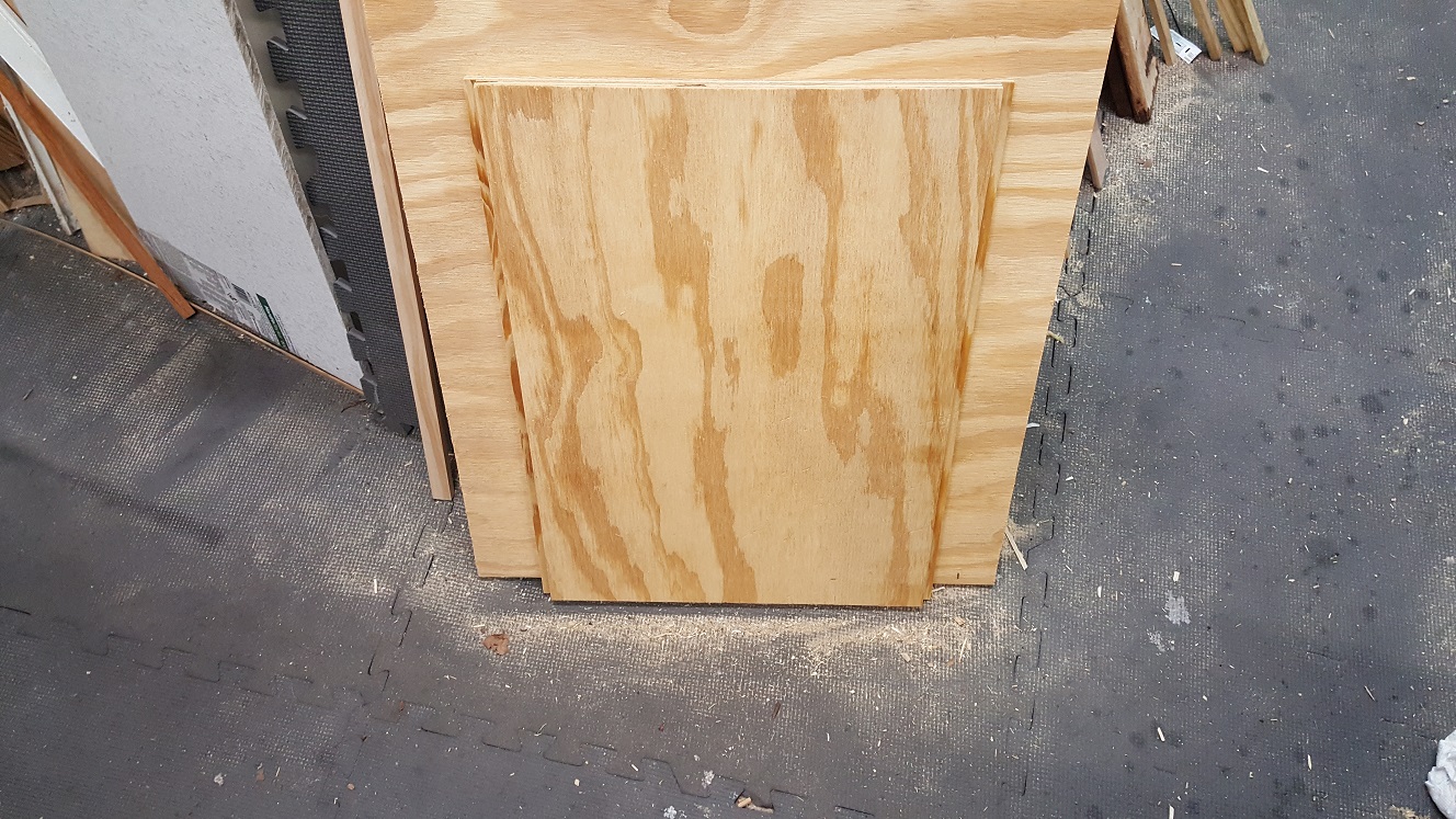


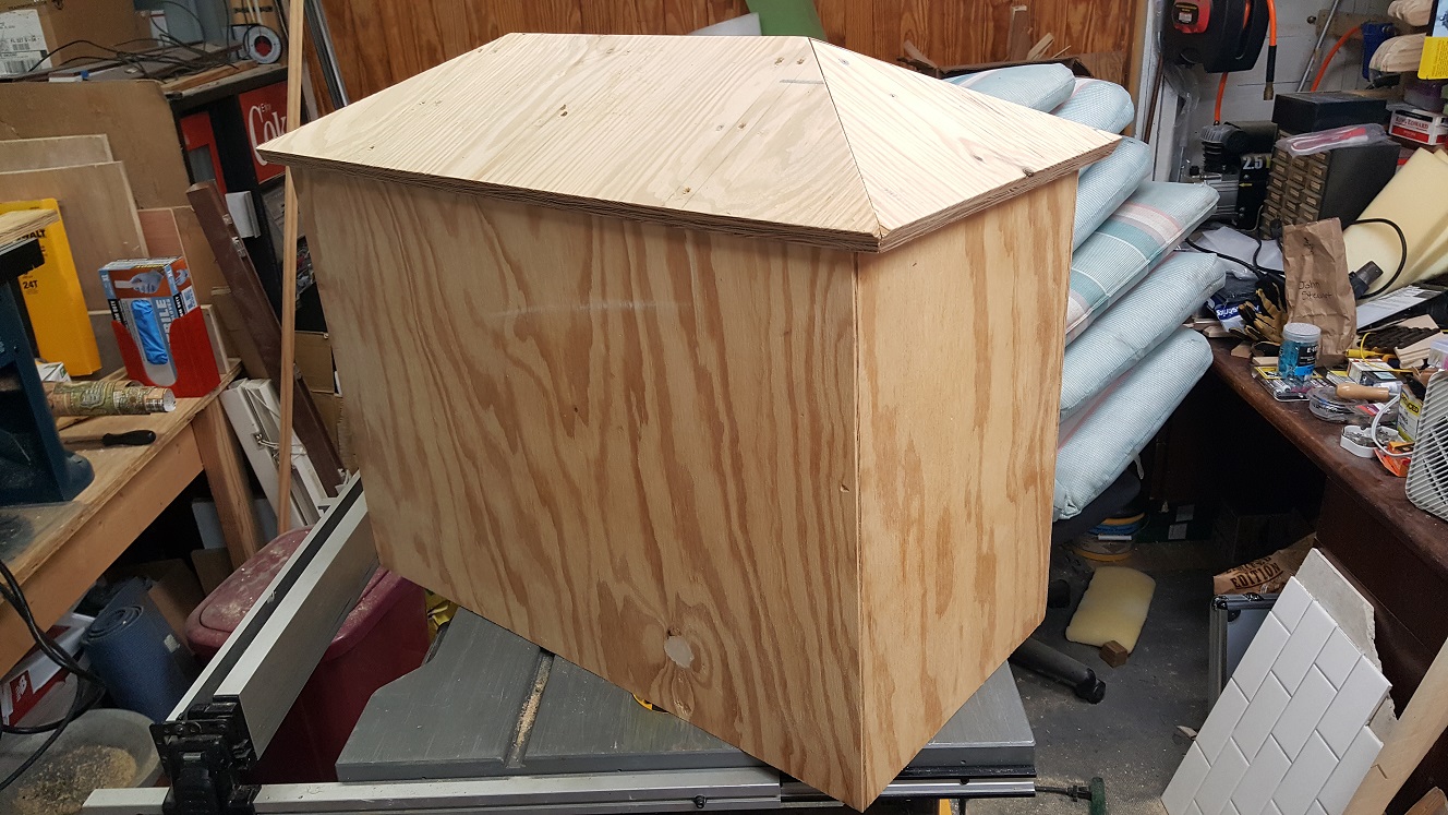


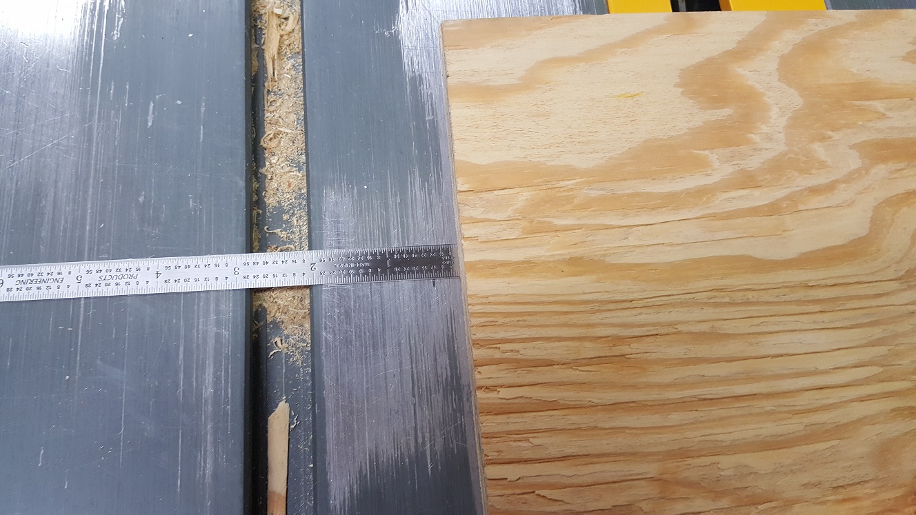
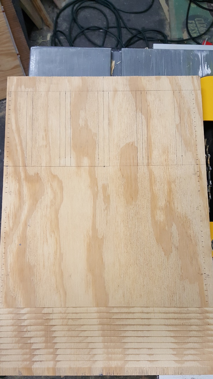

<< Previous | Garden Scale | Beginnings | New Beginnings | Third Incarnation | Additions | Pond | Downtown | Expansion | Tower | Future | Next >>