<< Previous | Garden Scale | Beginnings | New Beginnings | Third Incarnation | Additions | Station | Pond | Downtown | Expansion | Tower | Future | Next >>
Our Backyard Garden Railroad Empire
New Beginnings...
(September 2014)
Our garden scale "empire" started on the pool deck of our house in Wekiva back in 2013. By late 2014 I had
the track laid all around the side yard and a water feature nearly complete except for the plumbing and pump.
Then things changed... We bought our home here in Mount Dora with the idea that we could take our time fixing
her up, without having to worry about living there at the same time. Fate had other plans for us when a pipe
burst in the atrium, and we were forced to move much earlier than expected when Nick and I couldn't fix it
quickly enough to continue to live there.
Long story short, all of that work was for nothing. I had to pull all the track back up and put it away until I had time to plan a new pike here in Mount Dora. We lived here for over a year before I finally starting to get our garden railroad back online. I have a "folded dogbone" plan in mind where the loops of the dogbone are stacked on top of one another, the upper loop being mainly 14' diameter and the lower 20' diameter. The tracks will parallel each other, the lower loop rising and the upper loop descending until they meet about halfway in between and cross at grade at the other end of the yard and loop back. At least, that's the plan...
(July 2015)
I want a water feature here too, but my plan will force the "sump" to be behind the tracks along the fence. I
want the stream to "disappear" into the distance behind the track, which will be elevated, most likely on an
embankment that will hide the sump from view. To create that illusion, I will need a bridge over the water as
it traverses beneath the track and around the corner behind it and the embankment. There's only one problem. I
don't have a bridge, and anything I could buy is mighty expensive, so it looks like I'll be making my own.
I used the scrap fencing that was still in pretty good shape when we replaced it March of last year (2015).
(August 2015)
I've ripped the slats into scale 6x12s (actual ¼"x½") and the piles into scale 12x12s (actual
½"x½") using the table saw and some home made plywood push shoes to do it safely. The thicker
slats I cut into scale 8x18s for the trestle stringers. I even made scale bridge ties to place across the
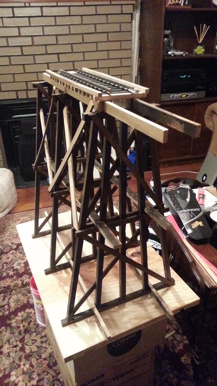
assembled stringers, but I'm getting ahead of myself. I started by making
a jig to both cut and assemble the scale 12x12s into trestle bents a scale 40' and 60' tall (actual 20"
and 30", respectively). I "expand" my "shop" into the living room, for both assembling and experimenting, and
we have the makings of a regular lumber mill, right here in scale.
Working in the living room allows me to experiment with different approaches to making trestle bents, combining the parts I like, and avoiding the ones I don't. And I can do it all from the comfort of my recliner while kicking back and relaxing in the evenings. The shortcomings of my template design and assembly technique soon become all too apparent. I rushed into making the original trestle bent template, using pieces I had on hand to allow me to quickly screw together something that would work. And something is better than nothing, believe me, but... Parts from one side that should be interchangeable with the other side weren't, and the screws that held the "guides" to the plywood base were barely long enough to hold them, so there was a lot of flex when cutting or assembling.
It was good enough to help me put together an assembly routine, holding the pieces together and in place while I hand drilled and glued together our first trestle bents. Each cross brace was laid in place and cut to fit by hand. Then the bent was removed from the template and flipped over to attach the cross bracing to the other side. Next I needed a way to assemble multiple bents together into an actual trestle, complete with "girts" and outside cross bracing. I used the dado cutter on the saw to make notches of the proper size in some of the stringer material, at the appropriate intervals to hold the sills together at the bottom and the caps together at the top, three bents at a time.
I made another jig for assembling a howe deck truss bridge using the same "rickety" style as the tresle bent jig, except this time I add "threaded pins" like the kind they use to hold together that cheap "pressboard" furniture, e.g. Sauder. I'm hoping the pins will keep everything aligned so I can again hand drill and assemble a bridge truss. I quickly realize it suffers from the same issues as the trestle bent template, plus it seems nearly impossible to get the holes for the pins drilled straight and in the correct position. I make the best of it and test the modular approach to assembling a bridge truss.
I "borrowed" the idea from an online kit form of these bridges. Basically, staggered "ends" are constructed with the idea that they can be overlayed onto each other such that the minimal length bridge is constructed. An "arbitrary" length center section is constructed using the same staggered pattern, and the pieces are brought together and assembled into a bridge of any length desired. I say arbitrary and any length, but the length limit is basically a multiple of the distance between diagonals, with the minimum being six times that distance between the diagonals and the maximum limited only by "realism". Too long and it looks "rickety". Too short and it looks too "stocky".
<< Previous | Garden Scale | Beginnings | New Beginnings | Third Incarnation | Additions | Station | Pond | Downtown | Expansion | Tower | Future | Next >>
(September 2015)
This worked well enough to put together a trestle approach, but now I would need scale sized stringers that were put
together like the prototype, using through bolts and spacer "washers". I bought the smallest brass bolts and nuts I
could find at Lowe's, but they were way too big, both scale wise and practical wise. I would need something much
smaller. I looked at McMasterCarr to see what they had available, and found they didn't have much in the way of small
brass hardware. I did order some lengths of #2 threaded brass rod that I would need for the tension rods for the bridge
though. I found all the rest of the brass hardware I needed on eBay, as well as a brand new set of #2 dies to chase
the threads when I cut the threaded rod.
I cut the stringer stock to scale 16' and 32' lengths (8" and 16", respectively) then hand drilled the ends for the through bolts. The method I used to cut the threaded rod to size for the bolts was rather involved, using two of the thread chasing dies, one on either side of the cut I needed to make. Once cut, I could chase threads on both ends, then move the dies to the next cut and repeat. It took forever to cut one 3' length of rod into pieces the size I needed for assembling the stringers. And because I hand drilled the holes, alignment was terrible too, which just added to the assembly time and frustration.
And frustrating it was! The stringers are bolted together three wide, with the ends staggered by a scale 16', and washers in between each section. I start by threading nuts on each of the 8 rods I need for every 8" of stringer, then add a washer for every nuts, and push them through from the back of the first section. Then I place two more washers on top of the rods protruding through that section in preparation for adding the next sections. Note that I said sections, not section, since I need to stagger the next "layer" by half length. One 8" section for a nice even end, then another 16" section hanging over the end of the first by another 8". With all those rods and nuts and washers in place, the last section can go on top, completing the assembly.
Sounds easy enough, but because of the alignment issues related to hand drilling the holes, it's all I can do to get everything together without losing all the washers from the previous steps or just flat out breaking off one of the pieces of threaded rod holding everything together. Of course it all needs to come back apart, since all of these pieces will eventually need to be stained. and somehow "weatherproofed" to survive the elements too. All in good time. I'm still working on how everything goes together! This is a bit more detail than I wanted to go into for now, but it illustrates the learning process I went through to know what to expect on a larger, let's say "production" scale.
I place the stringers I finally manage to put together on top of the trestle, along with a piece of track sitting on ties, as a sort of mockup to see how it all looks. It looks good for a section of trestle. It also looks like the rest of it needs stained to match the trestle. All in good time. We still need a bridge to span the trestle approaches and more stringers and bridge ties to support the track and equipment rolling over these spans. By now it is apparent I'll need better jigs and much better alignment when drilling holes and assembly.
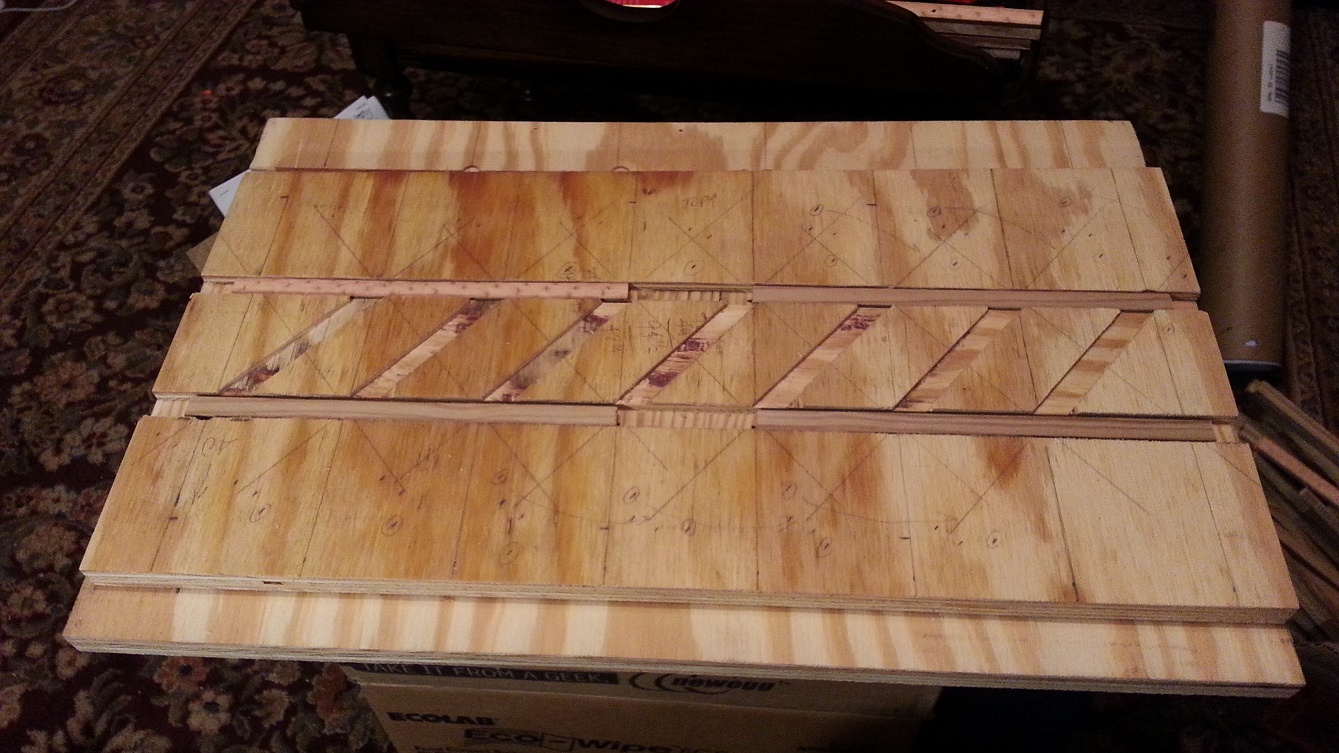
I made a jig out of ¾" plywood for assembling a howe through truss bridge using my router and carefully carving grooves for the various pieces to fit in. I draw everything out on the plywood first, then clamp a guide for the router, then plunge and remove just what needs removed. The long channels at the top and bottom I make 3⁄8" deep and the diagonals 1⁄8" deep. This will allow the top and bottom beams to lay flat and the diagonals to lay flat on top of them and align with them correctly. Sounds good anyway. Not sure how I manage to screw it up by cutting one of the long channels on the wrong side of the guide line though and have to make another pass to put the channel in the correct place right next to it.
I made another jig for cutting and assembling a howe deck truss bridge using the same using the same approach as the through truss, but this time I mark the channels too, not just the guidelines. No mistakes this time. I get it routed correctly and drill holes where the threaded rods will go. I still have to hand drill the bridge members for them, but at least everything lines up correctly. I knock out the first truss in a few days. I need to cut some more threaded rod for the second, so it takes a bit longer. Within a few weeks I'm able to put together a howe deck truss bridge, suitable for display purposes anyway. It still needs stained and I'm not sure it's actually correct to prototype since all the pictures of a howe deck truss bridge that I've seen show the ends as diagonals with a straight pile to the caps, not connected to the rest of the bridge via the top beams, just there to support the stringers above. Looks good though...
(October 2015)
So now that I have a scale 48' (actual 24") long deck bridge, I can see that if I make it much longer, it will
definitely look out of proportion. Time for a much longer (and much taller) howe through truss bridge. If I'm
going to span that water feature with it that is. I start hand drilling the beam pieces, again with the staggered
modular approach in mind. The deck truss was fairly rigid and did pretty well using the modular approach. The
through truss is much larger, but still uses the same sized members, so it is far less rigid and much more prone
to moving where it shouldn't. I manage to get a
short truss together, enough for proof of concept and testing out the new jig.
As I assemble the longer 4' version of it, the problem becomes keeping it together without the beams wanting to come apart, especially where the staggered joints overlap. Tightening the nuts helps some, but I end up having to use larger washers over the outside joints in the beam to keep them from pushing apart as I tighten them. It works enough to get the first truss together, but I decide I need to just use one long piece in between the more prototypical sections that will be seen on the outside. This not only helps rigidity tremendously, but also eases assembly greatly, providing the "backbone" the structure needs.
Next I modified the template to fit together with the dremel drill press Ann got me quite a few Christmases back. This helps avoid the "slop" I'm getting with hand drilling. Now I drill the first hole, slide the beam down aligning that hole with the hole already drilled at the correct location in the template, using a piece of the threaded rod to index it in place for drilling the next hole. I also use this to correctly locate and drill the holes in the diagonal members helping everything go together that much easier. Now all I have to deal with is the members I've already hand drilled, but incorrectly aligning with the new "precision" drilled pieces. It's easiest just to redrill the hole in the correct location and continue assembly.
With both trusses assembled, I'm able to begin assembling them into a bridge. I start by cutting the "keepers" the tension rods will pass through, then drill the holes for them, and finally begin to "bolt" the bridge together. I start with the ends, just to hold everything together, then move to the middle. I work my way back toward the ends, adding keepers halfway between them, then halfway between those, and so on... Eventually they are all in place and I have it fully assembled. I've long since moved "production" to the garage, for two reasons. First, Ann was tired of the mess I was making in the living room. Second, I didn't have enough room to assemble a 4' long bridge in the living room, let alone find a place for the dremel drill press!
(November 2015)
After the success of using a "backbone" piece when constructing the bridge trusses, I decide to use that approach for
the stringers as well. I make another jig to fit the dremel drill press to allow me to "precision" drill the stringer
pieces. Not only does this help better align the holes for the rods, it also helps speed assembly since now I can
pretty much put together 16" at once. I think I have the approach I want to use going forward and it's tested. Now
I need to figure out how I'm going to stain ALL these stringer pieces at the same time. I've already decided on using
dark "stained" linseed oil to both simulate prototypical creosote as well as emulate it's preservative properties.
I use a quart yogurt cup and fill it about half full or so with linseed oil. Then using a plastic spoon I add 10 to 15 spoonfuls of dark walnut minwax wood stain to it. If it's not dark enough when I apply it, I add more stain to the mix. This worked well for the trestle bents and the bridge trusses, so the bridge ties and stringers are next. But there are a LOT of stringer pieces and I've been pretty much "hanging" the pieces to dry so far. For the trestle bents, I just hung them upside down from a piece of furring strip sticking out rom the wall. Granted, it's only been a few at a time, so not much help there. The bridge truss piece I "threaded" onto short (~12") pieces of threaded rod hanging out the front of the wall cabinets to "drip dry".
But this time they are much heavier and there are way too many of them to use that approach. I decide to string them on a full 3' long piece of threaded rod which I then draped over the open cabinet doors on either side of the corner cabinet. The weight wanted to bend the threaded rod, so I tried to "balance" it by distributing the weight across both sides of the doors. It took some doing and a lot of care to get them all done, but it worked! Once they're "dry", the fun really begins! Assembling these stringers is still pretty much a chore, but at least I know everything fits together better and if a particular joint is being stubborn, I just "chase" the holes by hand with a drill bit and problem solved.
When all the pieces come together, it really is an impressive model, even if it's not entirely prototypically correct... I'm pleased with it and now we have a bridge and some trestle approaches to it, complete with bridge ties and stringers! Time to ramp up the efforts outside. I've laid out some of the loops to get an idea of where things will fit, but now I'll need to make another template, this time to assemble closer to real life stringers. Stringers to act as the track roadbed. I'll need one for 20' diameter and one for 14' diameter curves. I'll also need some plastic pipe to act as posts to hold the stringers off the ground.
I won't bore you with all the details here, but like all the other templates I've made, the first one taught me all the things I did worng and how I should have done it. In any case, I manage to get the track support stringers I need put together. Again, without going into too much detail, I try to continue the next ¼" x ½" x 8' where the first one ends, but it soon gets out of hand tracking which one goes where. Not to mention that now each section is "married" to the next, they are not interchangeable. Some of them aren't anyway, but it would be nice to be able to mix and match them, where I know I need two of the 20' sections and three 14' sections and a 20' to 14' transition section... Kind of like an "off the shelf" approach where I can construct a number of them at a time then just join them together.
In the end I have enough to complete the upper and lower loops of the design. With the help of some 1¼" PVC pipe, and the finished stringers, the loops are in place and waiting for me to extend them. On the side by the fence, I decide to extend the lower loop to curve from behind and run underneath of the bridge which will connect to the upper loop. I keep experimenting with placement. A brick here, a shim there. Wiggle this a bit closer to one end, stretch it away from the other. I am struggling with the exact lengths and limited curvatures of the trackage I have on hand. As far as availability, the Aristocraft stainless steel is already scarce, and quickly becoming a rare item. I keep trying to figure out a way to make my own track, boths rails and ties... More research in my future.
(January 2016)
Upper and lower loops installed, working on planning water feature and extending trackwork along the fence. In
looking at the way I want to extend the lower loop to cross beneath the upper loop trackage, over the long bridge span,
I realize I'll need a more realistic approach for the bridge. The current approaches are only three bents on either
end, and an abrupt drop off from nothing to a scale 40' in the span of a scale 16'. Coupled with a scale 40' retaining
wall, it just won't be prototypically correct, let alone look right. Most railroad standards call for a 1:1.5 "rise
over run" slope, so roughly only a scale 10' drop in the little over scale 15' between bents. To drop the entire scale
40' should take about five bents, roughly a scale 64', with the first bent having an integral wooden "retaining wall".
That will have to wait a bit though...
I put the finishing touches on the outside of the side porch restoration, so it looks good from the outside at least. Inside, not so much. I still need to do the rough in, let alone finishing touches, on the inside. There are a number of issues to resolve, not the least of which is the beadboard beneath the windows, and especially the trim around the windows. It's a bit tricky and I'm trying to figure it all out using a free program from Google, called "SketchUp". It's slow going, and even for the outside I had three different designs before I was able to choose one! This time, it's just taking everything into account, an how it all fits together. The hard part seems to be how to marry the old shiplap siding with the new. As with all things new meant to match the old, corners have to be cut, because profit. It's hard to make up for the new shiplap being ½" shorter than the old.
It's a balancing act between getting more done on the side porch done and the railroad. Just having the outside look nice isn't enough, Ann wants the whole thing done. Add to that we just finished the rewire of the house a few months ago. Other than jacking up the back porch, this was the last major project that had to be done in order to prevent a potential major failure, like the porch falling off the house or the old "knob and tube" wiring catching fire. I continue to plan out the inside trim, done to the last board, including a set of builtin "mini" shelves to fit behind the short lengths of shiplap on either end.
(March 2016)
I've been assembling a reasonable looking trestle approach to one side of the bridge. Ann is still after me to finish
the side porch and is becoming more irritated with my attention to the railroad instead of the porch. I've already
cut to size and made up all the trim pieces to fit. They get a few coats of paint Saturday and installed Sunday. All
that remains is getting the new beadboard cut to size and painted. Oh, and the baseboards. Don't forget the baseboards!
Some of the older beadboard leaves quite a bit more gap between the floor, mainly because I had to cut the rotted
parts off the bottom, with the idea that the baseboard will hide the gap anyway.
The weather has been beautiful, and I've already freed up many of the double hung sash windows. The problem is most of them can only be propped open because the sash weight cords have rotted and broken. For my next diversion, I get to disassemble the windows and replace the sash cords for the weights. It takes the entire weekend just to do the four windows in the dining room on one side of the house and the living room on the other. Of course I break a few of the trim pieces as well. One of the dining room windows has actually had the inside stops notched out, as if something wouldn't fit in the window otherwise? Dunno. With the windows now fully operational, the screens are showing their deficiencies. You'll never guess what I get to replace next!
In any case, I manage to make some progress on the railroad, in between all the repairs and upgrades to the house. Progress is limited to refining my "technique" of assembling multiple bents into a section of trestle. I'm struggling with how to keep everything together, correctly spaced, and strong enough to be self supporting. It's one of those "need more hands" situations just trying to keep everything in place long enough to fasten it together. And fassten together is a term I use loosely. Just moving the struture tends to pull it all back apart again. To say it's rickety would be an understatement. I begin to wonder if I'll need to assemble the trestle in place or somehow connect the sill plates with hidden stringers and caps with the track stringers just to hold everythng together.
(June 2016)
Say goodbye to our railroad for awhile... We've tried everything we can think of to manage the dirt in the backyard.
We want to put sod down, but Ann thinks it's too shady for anything to grow there. The trees must come down! Well,
some of them anyway, and the long branch that's hanging over the neighbor's backyard and garage. Before we can have
that done, we must get the railroad out of the way and move the shed to the opposite corner of the backyard. Before
it can move there, we need to finish removing the bamboo and fix the fence it's pushing over. The fence is about
three panels long, between the back of the garage and the fence along the back of the yard.
You can read more about those adventures, but the short version is the railroad has been put on hold while we try to make yard more than the giant patch of dirt it is now. It takes some time and a lot of work, but we manage to make it much more appealing. A yard you'd enjoy. A yard you wouldn't mind spending time in. But it looked worse, much worse, before it looked better. But when it looked better, it looked much better. I'll continue to describe our progress, and the third incarnation of our garden scale pike in the next installment...


 August 2015


 September 2015


 October 2015


 October 2015


 November 2015


 November 2015


 January 2016


 March 2016
<< Previous | Garden Scale | Beginnings | New Beginnings | Third Incarnation | Additions | Station | Pond | Downtown | Expansion | Tower | Future | Next >>